Solid plasma-based polarized reconfigurable antenna
A plasma and reconfigurable antenna technology, applied in the direction of antenna grounding switch structure connection, radiation element structure, etc., can solve the problem of limited polarization working state of polarization reconfigurable antenna
- Summary
- Abstract
- Description
- Claims
- Application Information
AI Technical Summary
Problems solved by technology
Method used
Image
Examples
Embodiment 1
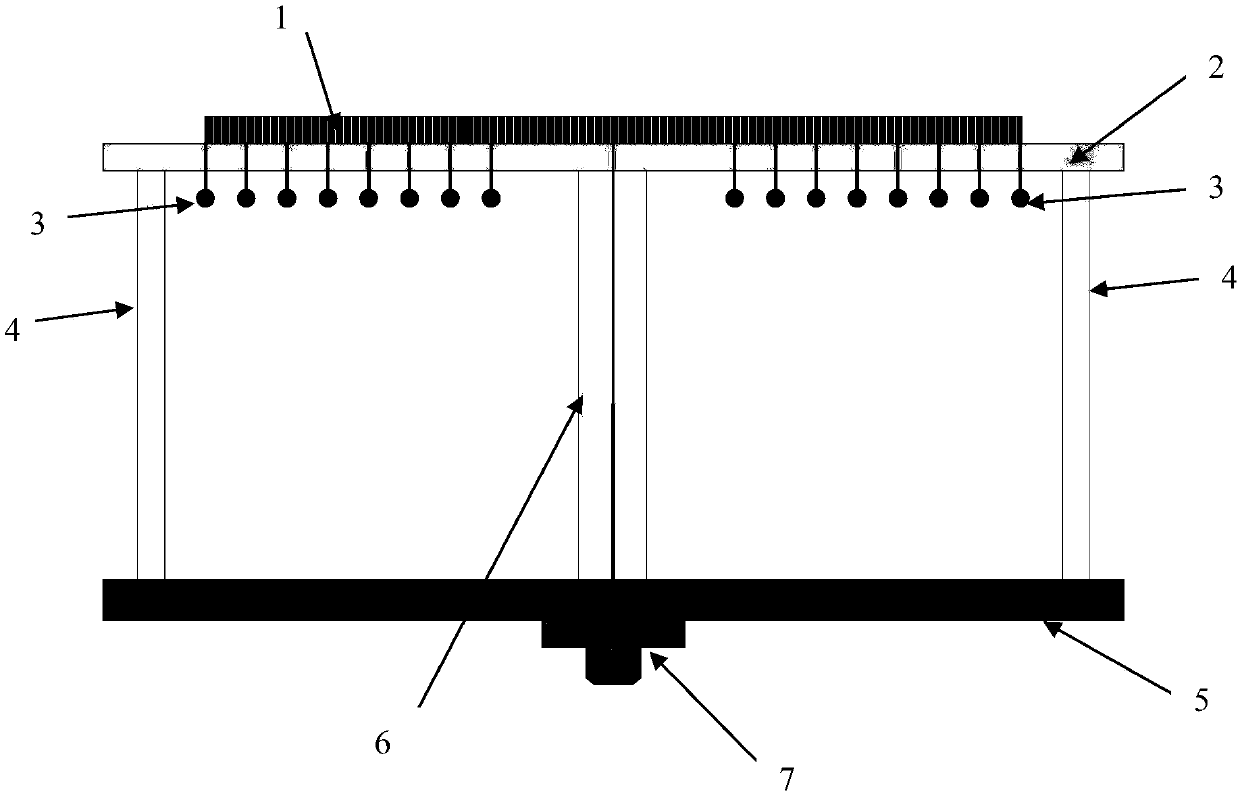
[0017] A polarization reconfigurable antenna based on solid plasma, including: feeder 6 and radio frequency connector 7, also includes: solid plasma generator array 1, substrate substrate 2, bias electrode 3, pillar 4 and metal base 5.
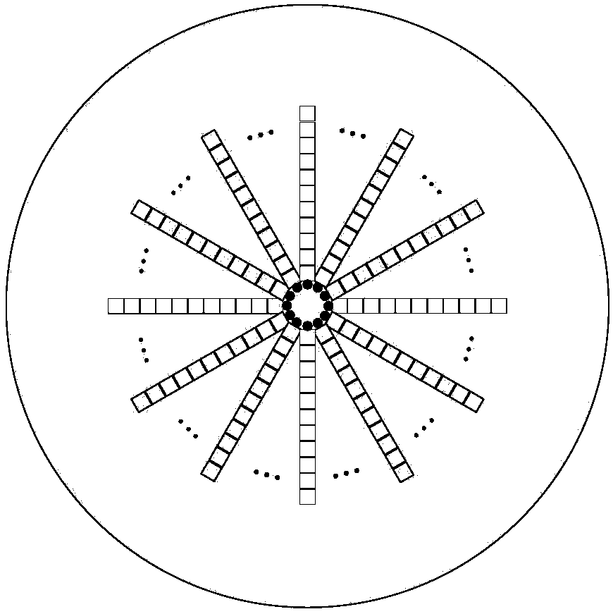
[0018] The solid plasma generator array 1 is formed by a plurality of solid plasma generators arranged radially, such as figure 2 .
[0019] The pillar 4 is a cylindrical shell structure with upper and lower ends open, the substrate substrate 2 is a plate-shaped structure with a plurality of through holes, and the substrate substrate 2 is covered and fixed on the upper port of the pillar 4; the solid plasma The generator array 1 is installed on the upper surface of the substrate 2, and a plurality of bias electrodes 3 are connected below the solid plasma generator array 1, and the plurality of bias electrodes 3 pass through the through holes on the substrate 2 correspondingly and Go deep into the cavity of pillar 4. The lower end of the pi...
Embodiment 2
[0022] A polarization reconfigurable antenna based on solid plasma, including: feeder 6 and radio frequency connector 7, also includes: solid plasma generator array 1, substrate substrate 2, bias electrode 3, pillar 4 and metal base 5.
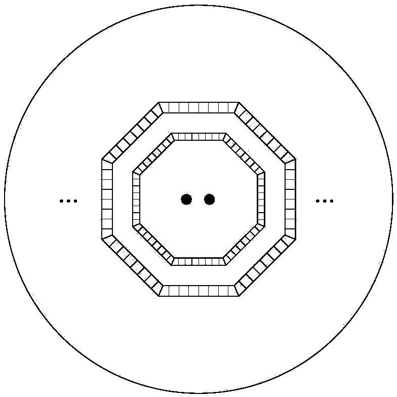
[0023] The solid plasma generator array 1 is formed by a plurality of solid plasma generators arranged in a plurality of concentric rings, such as image 3 .
[0024] The pillar 4 is a cylindrical shell structure with upper and lower ends open, the substrate substrate 2 is a plate-shaped structure with a plurality of through holes, and the substrate substrate 2 is covered and fixed on the upper port of the pillar 4; the solid plasma The generator array 1 is installed on the upper surface of the substrate 2, and a plurality of bias electrodes 3 are connected below the solid plasma generator array 1, and the plurality of bias electrodes 3 pass through the through holes on the substrate 2 correspondingly and Go deep into the cavity of pillar 4....
Embodiment 3
[0027] A polarization reconfigurable antenna based on solid plasma, including: feeder 6 and radio frequency connector 7, also includes: solid plasma generator array 1, substrate substrate 2, bias electrode 3, pillar 4 and metal base 5.
[0028] The solid plasma generator array 1 is formed by a plurality of solid plasma generators arranged radially and having multiple concentric rings of solid plasma generators with different diameters around the radiation center, as shown in Figure 4 .
[0029] The pillar 4 is a cylindrical shell structure with upper and lower ends open, the substrate substrate 2 is a plate-shaped structure with a plurality of through holes, and the substrate substrate 2 is covered and fixed on the upper port of the pillar 4; the solid plasma The generator array 1 is installed on the upper surface of the substrate 2, and a plurality of bias electrodes 3 are connected below the solid plasma generator array 1, and the plurality of bias electrodes 3 pass throug...
PUM
 Abstract
Description
Claims
Application Information
 - R&D
- Intellectual Property
- Life Sciences
- Materials
- Tech Scout
- Unparalleled Data Quality
- Higher Quality Content
- 60% Fewer Hallucinations
Browse by: Latest US Patents, China's latest patents, Technical Efficacy Thesaurus, Application Domain, Technology Topic, Popular Technical Reports.
© 2025 PatSnap. All rights reserved.Legal|Privacy policy|Modern Slavery Act Transparency Statement|Sitemap|About US| Contact US: help@patsnap.com


