Frequency/polarization hybrid reconfigurable antenna

A polarization mixing and reconfigurable antenna technology, which is applied to antennas, loop antennas, antenna grounding devices, etc., can solve the problem of few frequency points, imperfect continuous adjustable design, and difficulty in separating different characteristic parameters of hybrid reconfigurable antennas, etc. problem, to achieve the effect of narrow frequency step, independent reconfigurability, and frequency reconfigurability

Inactive Publication Date: 2021-07-09
BEIJING HUAHANG RADIO MEASUREMENT & RES INST
View PDF3 Cites 0 Cited by
  • Summary
  • Abstract
  • Description
  • Claims
  • Application Information

AI Technical Summary

Problems solved by technology

[0004] At present, most frequency reconfigurable antennas are frequency-discrete reconfigurable antennas, and the design of continuous adjustable antennas is not perfect, mainly because the step is wider and there are fewer selectable frequency points; the design of hybrid reconfigurable antennas is currently difficult to achieve Separation of different characteristic parameters, that is, when one parameter is adjusted, another parameter is kept stable

Method used


Image

  • Frequency/polarization hybrid reconfigurable antenna
  • Frequency/polarization hybrid reconfigurable antenna
  • Frequency/polarization hybrid reconfigurable antenna

Examples


Embodiment Construction

[0062] The present invention will be described in detail below in conjunction with the accompanying drawings and specific embodiments, but not as a limitation of the present invention.

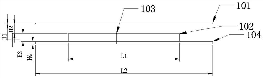
[0063] Such as figure 1 As shown, it is a schematic side view of a preferred embodiment of the present invention. The side length of the first medium plate is L1, and the plate thickness is H3; the side length of the second medium plate is L2, and the plate thickness is H4; the side length of the third medium plate is L2, and the plate thickness is H1. The third dielectric plate 101 is located above the first dielectric plate 102 and is H2 away from the first dielectric plate. The second dielectric board 104 is located under the first dielectric board 102 and is in close contact with the first dielectric board 102 . The metallized via hole 103 is located in the middle of the two dielectric boards and runs through the two dielectric boards. The floors are printed on the lower surface of the f...


PUM

PropertyMeasurementUnit
angleaaaaaaaaaa

Abstract

The invention discloses a frequency / polarization hybrid reconfigurable antenna. Metal patch floors are respectively printed on the lower surface of a first dielectric plate and the upper surface of a second dielectric plate; the second dielectric plate clings to the lower surface of the first dielectric plate; the first dielectric plate comprises a rhombic metal patch and a rhombic metal ring which are printed on the upper surface of the first dielectric plate; the rhombic metal ring is arranged on the periphery of the rhombic metal patch; a feeding point position of the rhombic metal patch is provided with a metalized via hole which is connected to the reconfigurable Wilkinson power divider of the second dielectric plate; midpoints of four sides of the rhombic metal ring are connected with midpoints of four sides of the rhombic metal patch through four variable capacitance diodes D1-D4; and a polarizable reconfigurable Wilkinson power divider is printed on the lower surface of the second dielectric plate. According to the invention, independent reconfiguration of frequency and polarization is realized, so that the antenna can be switched among different frequency bands and different polarization modes, the frequency step is narrow, and the antenna can work at different frequency points in the frequency band more accurately.

Description

technical field [0001] The invention relates to a frequency / polarization reconfigurable antenna. Background technique [0002] In the tide of the information society, wireless communication has had a huge impact on people's daily life, and the antenna, as a device for radiating and receiving electromagnetic waves, has received more and more attention from experts and scholars. Traditional microstrip antennas have narrow frequency bands, and it is often necessary to design multiple antennas with different frequency bands or different functions. However, this not only doubles the volume and cost of the antenna, but also generates electromagnetic interference between different antennas, which poses new challenges to the design of microstrip antennas. For this reason, reconfigurable antennas came into being. The design idea of ​​a reconfigurable antenna is to realize the functions that can only be realized by multiple antennas or antenna arrays through one or a few antennas, s...

Claims


Application Information

Patent Timeline
Patent Type & Authority Applications(China)
IPC IPC(8): H01Q1/38H01Q1/48H01Q1/50H01Q5/321H01Q7/00H01Q15/24
CPCH01Q5/321H01Q15/24H01Q1/48H01Q1/38H01Q1/50H01Q7/00
Inventor 王金灏赵柯褀臧洪明
Owner BEIJING HUAHANG RADIO MEASUREMENT & RES INST
Why Eureka
Try Eureka