A planar end-emitting pattern reconfigurable antenna

An end-fire direction and reconfigurable antenna technology, which is applied in the field of reconfigurable antennas with planar end-fire patterns, can solve the problems of high profile, large reconfigurable antenna volume, and low-profile end-fire antennas that cannot achieve flexible beam control. Achieve high radiation efficiency, easy processing and integration, and simple antenna structure

Active Publication Date: 2018-12-21
SOUTH CHINA UNIV OF TECH
View PDF5 Cites 11 Cited by
  • Summary
  • Abstract
  • Description
  • Claims
  • Application Information

AI Technical Summary

Problems solved by technology

[0003] In view of this, in order to solve the above-mentioned problems in the prior art, the present invention provides a planar end-fire pattern reconfigurable antenna, which solves the problem that the existing low-profile end-fire antenna cannot realize flexible beam control, and the existing pattern The problem of large volume and high profile of reconfigurable antenna

Method used


Image

  • A planar end-emitting pattern reconfigurable antenna
  • A planar end-emitting pattern reconfigurable antenna
  • A planar end-emitting pattern reconfigurable antenna

Examples


Embodiment Construction

[0029] The specific implementation of the present invention will be further described below in conjunction with the accompanying drawings and specific embodiments. It should be pointed out that the described embodiments are only a part of the embodiments of the present invention, rather than all embodiments. Based on the embodiments of the present invention, all those skilled in the art can obtain without creative work. Other embodiments all belong to the protection scope of the present invention.

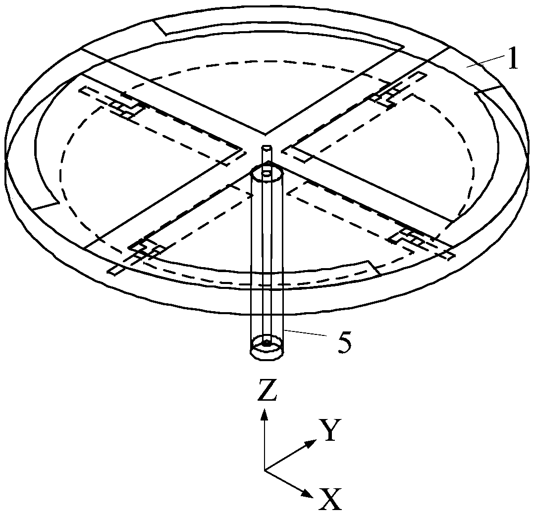
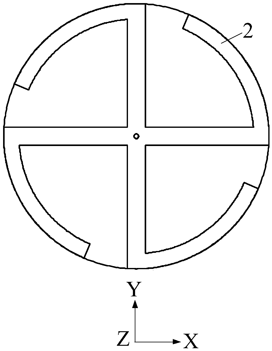
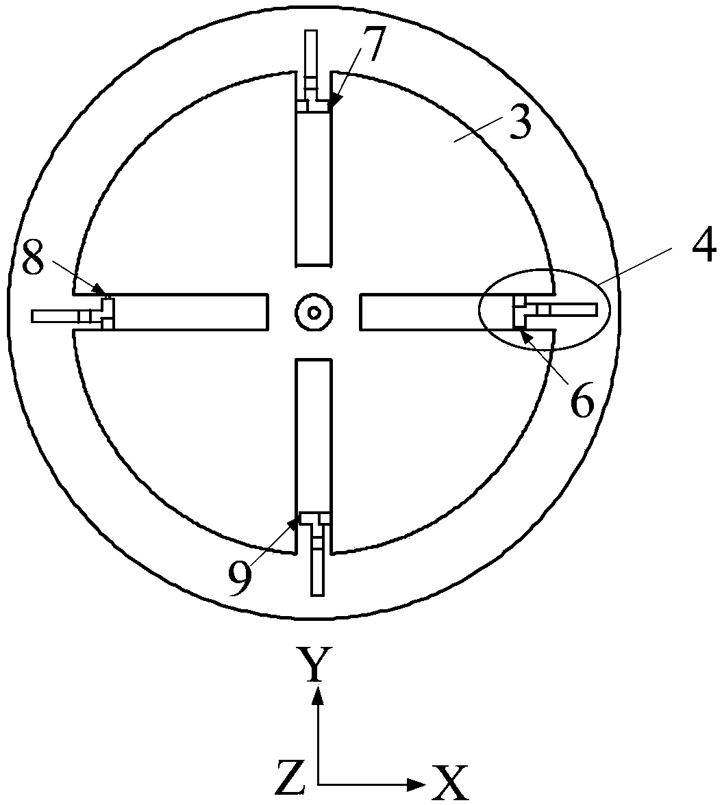
[0030] Such as Figure 1 to Figure 4 As shown, this embodiment uses F4BMX with a thickness of 3mm, a relative permittivity of 2.2, and a loss tangent of 0.0007 as the dielectric substrate 1, including the opposite first surface and the second surface, and the radiation patch 2 is attached to the dielectric substrate. 1, the grooved floor 3 is attached to the second surface of the dielectric substrate 1, the switch and bias circuit 4 are arranged in the groove of the grooved floor ...


PUM


Abstract

The invention discloses a planar end-emitting pattern reconfigurable antenna, include a dielectric substrate, radiation patch, slotted floor, switch and bias circuits and coaxial cables, the dielectric substrate includes an opposing first surface and a second surface, the radiation patch is attached to the first surface of the dielectric substrate, the grooved floor is attached to the second surface of the dielectric substrate, The switch and the bias circuit are arranged in the slotted floor slot, the coaxial cable comprises an outer conductor and an inner conductor, the outer conductor is connected with the slotted floor, the inner conductor is connected with the radiation patch through the dielectric substrate, and the coaxial cable is arranged at the geometric center of the planar end-emitting pattern reconfigurable antenna; The invention discloses a planar end-emitting pattern reconfigurable antenna, which not only has excellent circuit characteristics and radiation characteristics, but also has the advantages of compact size and simple structure, and reduces the complexity and cost of a radio frequency antenna module.

Description

technical field [0001] The invention relates to the field of wireless mobile communication, in particular to a reconfigurable antenna with a planar end-fire pattern. Background technique [0002] An end-fire antenna is an antenna whose maximum radiation direction is parallel to the plane where the radiator is located. Common types of end-fire antennas include Yagi antennas and helical antennas. End-fire antennas have a wide range of application requirements in the military and civilian fields, especially in some scenarios with limited space size, such as handheld devices, cordless phones, vehicle and aircraft systems, etc., often need to be applied to low-profile end-fire antennas . On the other hand, the pattern reconfigurable antenna has the characteristic of dynamically controlling beam scanning, which can effectively reduce multipath fading and electromagnetic interference, and improve channel capacity. Therefore, low-profile, end-fire, pattern-reconfigurable antennas ...

Claims


Application Information

Patent Timeline
Patent Type & Authority Applications(China)
IPC IPC(8): H01Q1/38H01Q1/48H01Q1/50H01Q3/24
CPCH01Q1/38H01Q1/48H01Q1/50H01Q3/24H01Q3/247H01Q9/0407H01Q3/242H01Q9/285
Inventor 潘咏梅欧阳鋆郑少勇
Owner SOUTH CHINA UNIV OF TECH
Why Eureka
Try Eureka