Electric wire groove device

A technology for wire troughs and weak wires, applied in the field of wire troughs, can solve problems such as difficult arrangement, inconvenient weak wires passing through, troubles, etc.

Pending Publication Date: 2018-01-19
天津企鸿科技有限公司
View PDF0 Cites 4 Cited by
  • Summary
  • Abstract
  • Description
  • Claims
  • Application Information

AI Technical Summary

Problems solved by technology

[0002] The weak wire trough we usually see is just a simple rectangular iron trough. All the wires are placed in one trough, which is not easy to organize, and the closed iron trough is not convenient for weak wires to pass through, which is troublesome to use.

Method used


Image

  • Electric wire groove device
  • Electric wire groove device

Examples


Embodiment Construction

[0011] Below according to accompanying drawing and embodiment the present invention will be described in further detail:

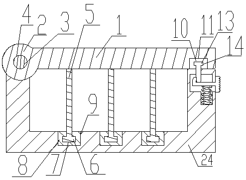
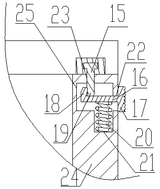
[0012] A wire trough device, comprising an upper trough cover 1, an upper trough cover left protrusion 2, a shaft rod 3, a baffle plate 5, a positioning block 8, a pad 10, a positioning rod 15, a pull rod 16, a telescopic spring 20, and a weak wire trough Main body 24, the upper slot cover 1 has the left protrusion 2 of the upper slot cover, the left protrusion 2 of the upper slot cover has a shaft hole 4, the shaft 3 is adapted to the shaft hole 4, the shaft 3 Insert the shaft hole 4, the lower part of the baffle 5 has a baffle protrusion 6, the positioning block 8 has a baffle protrusion groove 7, and the baffle protrusion groove 7 is adapted to the baffle protrusion 6, The baffle protrusion groove 7 is connected to the baffle protrusion 6, and the weak wire groove main body 24 has a plurality of positioning block grooves 9 inside, the positioning block ...


PUM


Abstract

The invention discloses an electric wire groove device which comprises an upper groove cover, an upper groove cover left protrusion, a shaft lever, barriers, positioning blocks, a cushion block, a positioning rod, a draw bar, an expansion spring and a weak electric wire groove body. The upper groove cover is provided with the upper groove cover left protrusion, a shaft lever hole is formed in theupper groove cover left protrusion, the shaft lever is adaptive to the shaft lever hole and is inserted into the shaft lever hole, barrier protrusions are arranged on the lower portions of the barriers, barrier protrusion grooves are formed in the positioning blocks, are adaptive to the barrier protrusions and are connected with the barrier protrusions, a plurality of positioning block grooves areformed inside the weak electric wire groove body, the positioning blocks are adaptive to the positioning block grooves and are connected with the positioning block grooves, a cushion block groove isformed in the right side of the upper groove cover and is adaptive to the cushion block, the cushion block is inserted in the cushion block groove, and a positioning rod groove is formed in the cushion block.

Description

technical field [0001] The invention relates to the field of wire troughs, in particular to a wire trough device. Background technique [0002] The weak wire trough we usually see is just a simple rectangular iron trough. All the wires are placed in one trough, which is not easy to organize, and the closed iron trough is not convenient for weak wires to pass through, which is troublesome to use. Contents of the invention [0003] The present invention aims at the above-mentioned deficiencies in the prior art, and provides a wire trough device with strong practicability and reasonable structure. [0004] The purpose of the present invention is to realize through the following technical solutions: [0005] A wire trough device, comprising an upper trough cover, a left protrusion of the upper trough cover, a shaft rod, a baffle plate, a positioning block, a cushion block, a positioning rod, a pull rod, a telescopic spring, and a main body of a weak wire trough, and the upp...

Claims


Application Information

Patent Timeline
IPC IPC(8): H02G3/04H02G9/04H02G9/06
Inventor 王海侠
Owner 天津企鸿科技有限公司
Why Eureka
Try Eureka