
Optical fiber fusion point protection device

A protection device and optical fiber fusion splicing technology, which is applied in the coupling of optical waveguides, etc., can solve the problems of inability to save the internal space of the transfer box, large volume, and irregular positions.

Inactive Publication Date: 2017-03-22
INNO INSTR (CHINA) INC
View PDF5 Cites 0 Cited by
  • Summary
  • Abstract
  • Description
  • Claims
  • Application Information

AI Technical Summary

Problems solved by technology

[0003] For example, there are a large number of cables in the optical fiber splice box, and the splicing point of each cable is equipped with an optical fiber splicing point protection device. These splicing points are located irregularly and the cables are placed in a mess
Moreover, the existing optical fiber fusion splice point protection device has a large volume, which cannot save the internal space of the transfer box

Method used


Image

  • Optical fiber fusion point protection device
  • Optical fiber fusion point protection device
  • Optical fiber fusion point protection device

Examples


Embodiment Construction

[0020] In order to make the object, technical solution and advantages of the present invention clearer, the present invention will be further described in detail below in conjunction with the accompanying drawings. Obviously, the described embodiments are only some embodiments of the present invention, rather than all embodiments . Based on the embodiments of the present invention, all other embodiments obtained by persons of ordinary skill in the art without making creative efforts belong to the protection scope of the present invention.

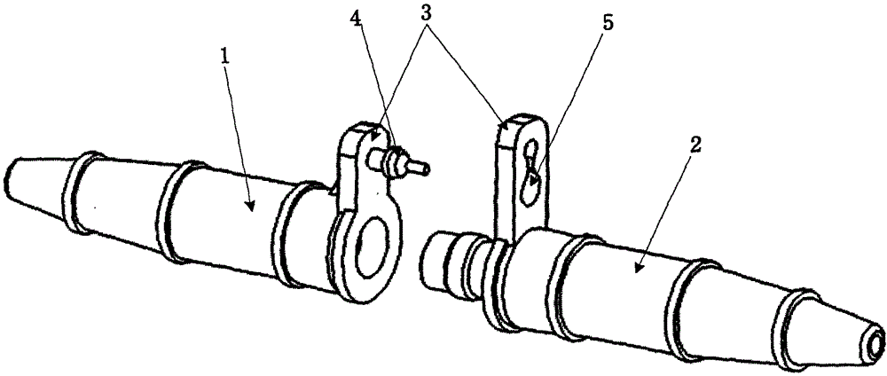
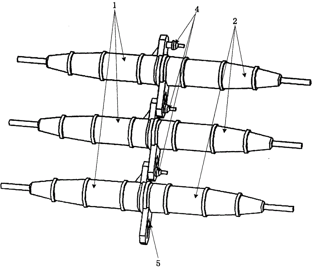
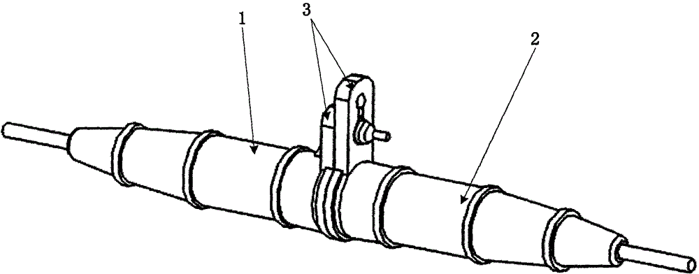
[0021] Combine below figure 1 , figure 2 , image 3 and Figure 4 The optical fiber fusion splice point protection device provided by the embodiment of the present invention will be described in detail. The optical fiber splice protection device is suitable for clamping optical fibers with an outer diameter of about 0.9mm.

[0022] like figure 1 As shown, the optical fiber fusion splice protection device includes: a first body 1 and ...


PUM


Abstract

The embodiment of the invention discloses a protecting device for an optical fiber fusion point. The protecting device for the fiber fusion point comprises a first body and a second body, wherein the first body is connected with the second body so as to form containing space for containing a thermal-shrinkage casing pipe, clamping devices are arranged on the outer side of the first body and the outer side of the second body, and multiple protecting devices for optical fiber fusion points are connected through the clamping devices in a clamped mode. The protecting devices for the optical fiber fusion points can be connected so that cables can be placed in order, concisely and attractively.

Description

technical field [0001] The invention relates to the field of protection devices for connecting parts of optical fiber cables, in particular to a protection device for optical fiber fusion points. Background technique [0002] The optical fiber fusion splice protection device is used to protect the optical fiber fusion splice point, and the cable with the fusion splice point will use the optical fiber fusion splice point protection device. The existing optical fiber fusion point protection devices are all independent devices. When a large number of cables are used on the equipment, the fusion point of each cable is equipped with an optical fiber fusion point protection device. Since the optical fiber fusion point protection device is independent Yes, usually the cables on the equipment are very messy. [0003] For example, there are a large number of cables in the optical fiber splice box, and the splicing point of each cable is equipped with an optical fiber splicing point ...

Claims


Application Information

Patent Timeline
Patent Type & Authority Patents(China)
IPC IPC(8): G02B6/255
Inventor 金勋
Owner INNO INSTR (CHINA) INC
Learn More