

Self-locking brake wheelchair
A technology for brakes and wheelchairs, applied in the field of medical devices, can solve the problems of poor safety performance, complex structure, and inability to be portable and stored.
- Summary
- Abstract
- Description
- Claims
- Application Information
AI Technical Summary
Problems solved by technology
Method used
Image

Examples
Embodiment Construction
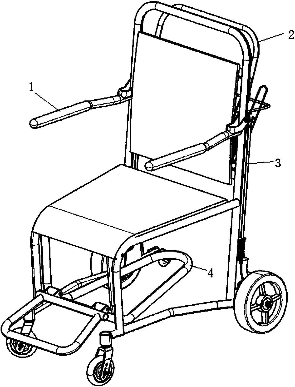
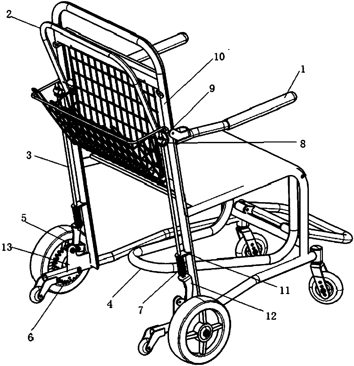
[0018] to combine figure 1 and figure 2 , a self-locking brake wheelchair of the present invention comprises a support seat, a chair body frame, a brake mechanism and a multi-wheel transmission mechanism; the chair body frame includes a backrest 10 tube, a seat tube, an armrest 1 and a base support tube; the support seat is fixed on the chair The backrest 10 tube of the body frame and the seat tube; the armrest 1 is installed on the backrest 10 tube; the brake mechanism includes a brake elbow 2, a brake straight rod 3, a brake connector 9, a rolling block 8, a brake piece 11, and a compression spring 7. Brake lifting pads 12, brake pads 5, brake fixing pads 13 and brake pads 5; the multi-wheel transmission mechanism includes front wheels, rear wheels and anti-rolling wheels; the lower end of the backrest 10 tube is provided with a brake support piece 11; the backrest 10 The connection between the tube and the base support tube is provided with a rear wheel; the connection be...
PUM
 Abstract
Description
Claims
Application Information