Disposable quantitative dosing group cup

A one-time, quantitative hole technology, used in laboratory utensils, laboratory containers, chemical instruments and methods, etc., can solve problems such as cumbersome operation, bacterial contamination, and easy environmental pollution.

Active Publication Date: 2019-06-21
张健 +1
View PDF3 Cites 0 Cited by
  • Summary
  • Abstract
  • Description
  • Claims
  • Application Information

AI Technical Summary

Problems solved by technology

[0002] In laboratory testing, there are many tests that need to quantitatively add the same test liquid to multiple test tubes. The current method is to use a quantitative pipette to add the test liquid to the test tubes one by one. This liquid addition method operates It is cumbersome, time-consuming, and the test is easily polluted by the environment, especially the bacterial identification test and drug sensitivity test are more likely to be polluted by bacteria in the environment. It is necessary to improve the known test equipment and test methods

Method used


Image

  • Disposable quantitative dosing group cup
  • Disposable quantitative dosing group cup
  • Disposable quantitative dosing group cup

Examples


Embodiment 1

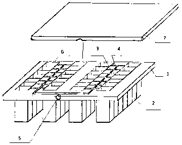
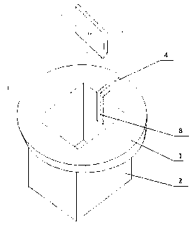
[0013] Example 1, such as figure 1 As shown in the figure, a connection plate 1 made of transparent material is installed in the disposable quantitative dosing group cup. One side of the connection plate is connected with multiple sets of test cups 2, and the surface of the other side of the connection plate is opened with a plurality of groove-like flow channels. , the flow channel is composed of a main channel 3 and a branch channel 4, the mouth 6 of the test cup 2 is opened on the side forming the flow channel through the connecting plate 1, the main channel 3 and the liquid inlet 5 opened on the connecting plate One end of the tributary channel 4 is connected with the main channel 3, and the other end of the tributary channel 4 is connected with the cup mouth 6 of the test cup. There is a groove 11 extending downward about 6mm long at the intersection along the cup wall. The plate 10 is attached to the groove to form a descending branch channel 8, such as figure 2 As sho...

Embodiment 2

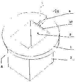
[0016] Embodiment 2, the main structure of this embodiment is the same as that of Embodiment 1, the only difference is the structure of the quantitative hole 9 and the connected descending branch flow channel 8, as described in the scheme, this embodiment is directly connected to one end of the branch flow channel 4 There is a section of blind hole 12 on the wall of the connected test cup, instead of the descending branch flow channel 8 in embodiment 1, a certain amount of hole 9 is horizontally opened on the test cup wall at the lower end of the blind hole, and connected with the blind hole, such as Figure 5 , 6 As shown, the quantitative hole is connected to the inner cavity of the test cup, and a cover plate 7 is pasted on the surface of the connecting plate 1 to seal all the flow channels and the cup mouth.

[0017] In this embodiment, the diameter of the blind hole 12 is about 1 mm, and the depth is about 6 mm. The diameter of the quantitative hole 9 is about 1 mm, and t...


PUM


Abstract

The invention discloses a cup set with a single quantitative addition function, made of a transparent material and comprising a connection plate (1); one side of the connection plate is connected withmultiple test cup units (2), the surface of the other side of the connection plate is provided with multiple passage units, each passage unit is formed by mutually communicating a main passage (3), abranch passage (4) and a downflow branch passage (8), one end of every passage unit is connected with a liquid inlet (5) arranged in the connection plate, the other end of every passage unit is communicated with an inner cavity of the corresponding test cup (2) through its quantitative hole (9), suitable dry test agent is attached to the bottom of each test cup (2), the passage units form a fluidflowing pipeline after the passage unit surface of the connection plate is sealed with a cover plate (7), such pipeline serves as a unique channel open to the outside from the test cups (2), and accordingly, quantitative liquid can be added into multiple test cups at a time.

Description

technical field [0001] The present invention relates generally to devices for testing in medical procedures. Background technique [0002] In laboratory testing, there are many tests that need to quantitatively add the same test liquid to multiple test tubes. The current method is to use a quantitative pipette to add the test liquid to the test tubes one by one. This liquid addition method operates It is cumbersome, time-consuming, and the test is easily polluted by the environment, especially the bacteria identification test and drug sensitivity test are more likely to be polluted by bacteria in the environment. It is necessary to improve the known test devices and test methods. Contents of the invention [0003] The object of the present invention is to provide a disposable quantitative liquid-filling group cup that can overcome the shortcomings of the known technology, and the test operation is simple and fast, and the test process is not easy to be polluted. [0004] ...

Claims


Application Information

Patent Timeline
Patent Type & Authority Patents(China)
IPC IPC(8): B01L3/00
Inventor 张健肖影
Owner 张健
Why Eureka
Try Eureka