Check patentability & draft patents in minutes with Patsnap Eureka AI!

Deodorant floor drain

A floor drain and anti-odor technology, which is applied in waterway systems, buildings, water supply devices, etc., can solve the problems of spring elasticity becoming smaller, moldy, and the blocking parts cannot completely block the main body, etc., and achieve the effect that the pre-tightening force is not easy

Active Publication Date: 2019-08-16
霍永军
View PDF6 Cites 0 Cited by
  • Summary
  • Abstract
  • Description
  • Claims
  • Application Information

AI Technical Summary

Problems solved by technology

[0003] It is very difficult to select the spring for the floor drain in the prior art. The reason is that when the selected spring makes the pre-tightening force for blocking the main body blocked by the blocking member, although it can be used in the early stage of the floor drain when the main body does not flow The main body can be blocked when there is water, and the main body can be opened even if there is less inflow. However, after the floor drain has been used for a period of time, the spring will gradually fail elastically, making the spring force gradually smaller, so that the blocking member cannot completely block the main body , so that it cannot play the role of deodorization
And when the selected spring makes the pre-tightening force of the plugging main body larger, although the main body can still be blocked when the spring has a slight failure, but in the initial stage of floor drain use, the pre-tightening force for the plugging main body is relatively large, making When the water flowing into the main body cannot force the plug to open and the water is discharged into the drain pipe, the undischarged water remains in the main body for a long time and becomes moldy

Method used


Image

  • Deodorant floor drain
  • Deodorant floor drain
  • Deodorant floor drain

Examples


Embodiment Construction

[0025] In order to enable those skilled in the art to better understand the technical solutions of the present invention, the present invention will be described in detail below in conjunction with the accompanying drawings and specific embodiments.

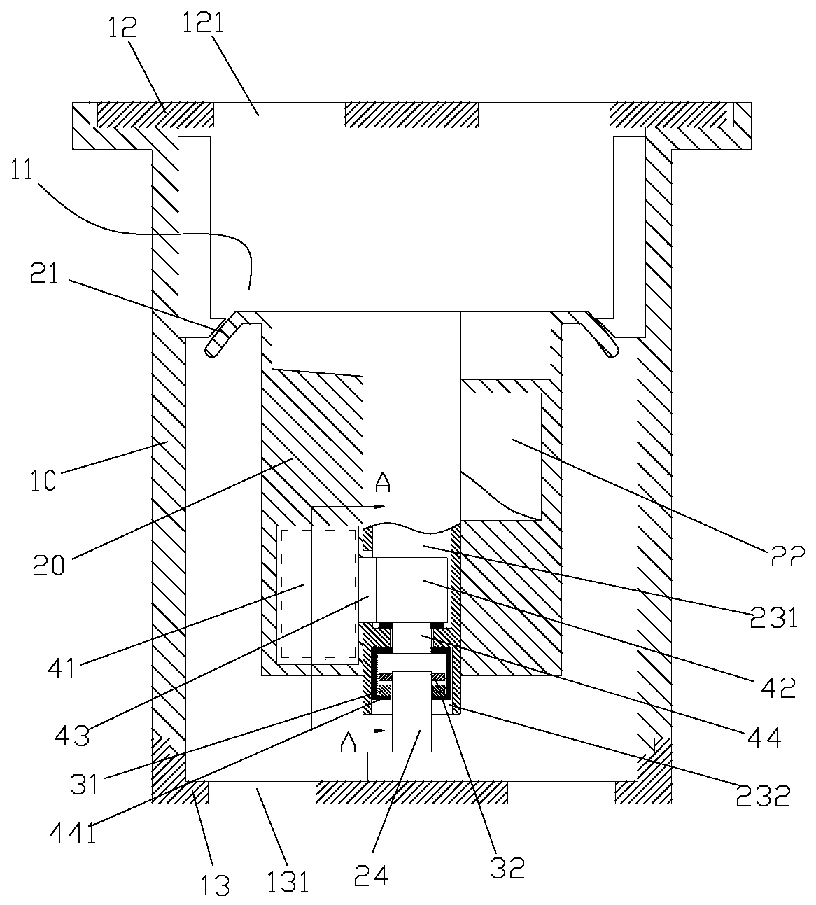
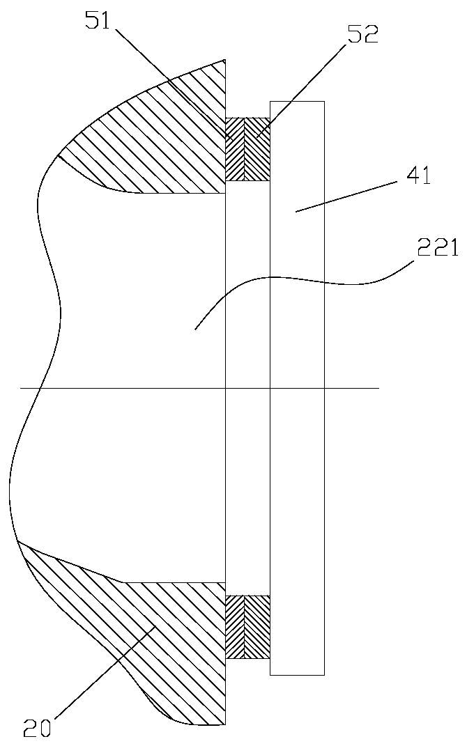
[0026] Such as Figure 1-4 As shown, the embodiment of the present invention discloses an odor-proof floor drain, which is used to discharge water on the ground into a drainage channel below the ground. pieces. The main body 10 is cylindrical, and its upper end is provided with an upper cover 12, the upper cover 12 is provided with a filter hole 121, the lower end of the main body 10 is provided with a bottom cover 13, and the bottom cover 13 is provided with a hollow part 131. The water on the ground enters the main body 10 through the outlet 11 through the filter hole 121 , and can be discharged into the drainage channel through the outlet 11 and the hollow part 131 . The blocking member 20 is columnar. The blocking member 20...


PUM


Abstract

The invention discloses an odor-resistant floor drain. The floor drain comprises a floor drain main body, a blocking part and a blocking application part; the floor drain main body is provided with anoverflowing hole, so that water on the ground flows into a drainage channel through the overflowing hole; the blocking part is arranged in the floor drain body, moves upward to block the overflowinghole, and moves downward to open the overflowing hole; the blocking application part comprises a first magnetic ring and a second magnetic ring, the first magnetic ring is arranged on the blocking part, the second magnetic ring is arranged on the floor drain main body and is opposite to the first magnetic ring in the vertical direction, and the first magnetic ring and the second magnetic ring canbe at least opposite to each other in a heteropolar mode so that the blocking part can block the overflowing hole. According to the odor-resistant floor drain, the magnetic effect between the first magnetic ring and the second magnetic ring is used for providing pretightening force for the blocking part to block the overflowing hole, the first magnetic ring and the second magnetic ring are permanent magnets, the magnetic action between the first magnetic ring and the second magnetic ring is almost not influenced by the use frequency and use time, and accordingly the pretightening force of theblocking part for blocking overflowing is not easily changed.

Description

technical field [0001] The invention relates to the technical field of water supply and drainage, in particular to an odor-proof floor drain for drainage. Background technique [0002] The floor drain is an important interface connecting the water end and the drainage piping system, and is usually embedded in the ground. In order to prevent the odor in the drainage pipe from spreading to the ground through the floor drain, the floor drain usually includes a main body and a blocking member, which blocks the main body under the force of a spring arranged under it to prevent drainage. The water in the pipeline diffuses through the main body above the ground to pollute the environment above the ground, and when the water on the ground flows into the main body, the water forces the plug to open, and then the water can pass through the main body, and when the water on the ground is drained Finally, the blocking member blocks the main body again under the action of the spring forc...

Claims


Application Information

Patent Timeline
Patent Type & Authority Patents(China)
IPC IPC(8): E03F5/04
Inventor 霍永军
Owner 霍永军
Features
  • R&D
  • Intellectual Property
  • Life Sciences
  • Materials
  • Tech Scout
  • Unparalleled Data Quality
  • Higher Quality Content
  • 60% Fewer Hallucinations
Learn More