
Locking mechanism

一种锁止机构、安全带的技术,应用在车内安全带、皮带收紧器、运输和包装等方向,能够解决花费等问题,达到精确设定、避免板簧滑出、小变化的效果

Active Publication Date: 2015-05-27
TRW AUTOMOTIVE GMBH
View PDF5 Cites 2 Cited by
  • Summary
  • Abstract
  • Description
  • Claims
  • Application Information

AI Technical Summary

Problems solved by technology

However, due to manufacturing tolerances and movement of the clamping points of the leaf springs, this regulation can only be complied with at great expense

Method used


Image

  • Locking mechanism
  • Locking mechanism
  • Locking mechanism

Examples


Embodiment Construction

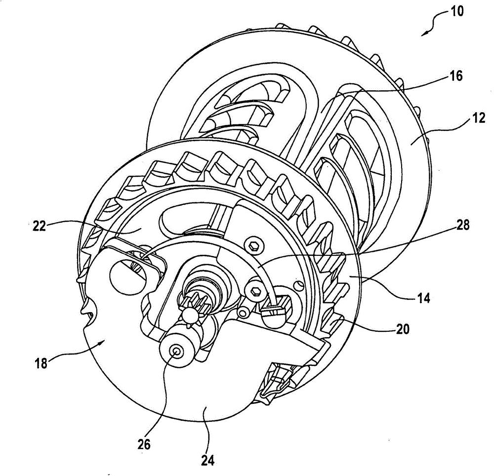
[0020] figure 1 A seat belt reel 10 for seat belts in a vehicle is shown. The seat belt reel 10 includes a first flange 12, a second flange 14 and a base body 16 arranged between the respective flanges 12, 14, on which a webbing of a seat belt can be wound. Arranged on the second flange 14 is a locking mechanism 18 which can trigger a locking mechanism in the event of an accelerated rotational movement of the belt reel 10 , for example caused by a sudden belt pull-out, which can engage It engages in the toothing 20 on the second flange 14 and can lock the belt reel 10 to prevent the belt from being pulled out further.

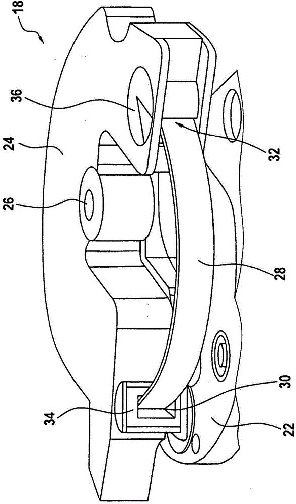
[0021] exist figure 1 and 2 It can be seen that the locking mechanism 18 has a bracket 22 which is coupled to the second flange 14 of the belt reel 10 . Furthermore, an inertial mass 24 is arranged on the second flange 14 , which is pivotable relative to the carrier 22 about a bearing 26 . The inertial mass 24 is coupled to the carrier 22 via a prestressed...


PUM


Abstract

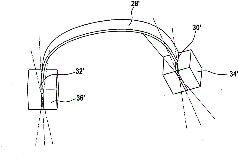
A locking mechanism (18) for a belt reel (10) of a belt retractor in a vehicle, having a support (22) which is coupled to the belt reel (10) of the belt retractor, an inertial mass (24) which is pivotable to a limited degree relative to the support (22), and a leaf spring (28) which acts upon the inertial mass (24) in an initial position, comprises a respective receiver (34, 36) for the spring ends (30, 32) of the leaf spring (28) on the support (22) and on the inertial mass (24), in which receiver the spring ends (30, 32) of the leaf spring (28) are mounted so as to be pivotable to a limited degree.

Description

technical field [0001] The present invention relates to a locking mechanism for a seat belt reel of a seat belt retractor in a vehicle, the locking mechanism comprising a bracket coupled with the seat belt reel of the seat belt retractor and capable of limited pivoting relative to the bracket The inertial mass body and the leaf spring that loads the inertial mass body in the initial position. Background technique [0002] The locking of the belt reel in the vehicle is controlled, for example, by a locking mechanism which has a carrier coupled to the belt reel, which is coupled via a spring to an inertial mass opposite the carrier Can pivot to a limited extent. [0003] The spring is dimensioned such that the inertial mass rotates together with the bracket and the belt reel during normal operation of the belt retractor. When the belt reel accelerates due to a sudden belt pullout, for example caused by a sharp deceleration of the vehicle and the resulting movement of the veh...

Claims


Application Information

Patent Timeline
Patent Type & Authority Applications(China)
IPC IPC(8): B60R22/38B60R22/405
CPCB60R22/38
Inventor T·基尔魏因E·科赫
Owner TRW AUTOMOTIVE GMBH
Learn More