Check patentability & draft patents in minutes with Patsnap Eureka AI!

Warp knitting machine

A warp knitting machine and actuator technology, applied in the field of warp knitting machines, can solve problems such as the quality reduction of knitted fabrics

Active Publication Date: 2014-10-15
KARL MAYER STOLL R&D GMBH
View PDF8 Cites 0 Cited by
  • Summary
  • Abstract
  • Description
  • Claims
  • Application Information

AI Technical Summary

Problems solved by technology

Already small misadjustments lead to reduced quality of knitted fabrics

Method used


Image

  • Warp knitting machine
  • Warp knitting machine

Examples


Embodiment Construction

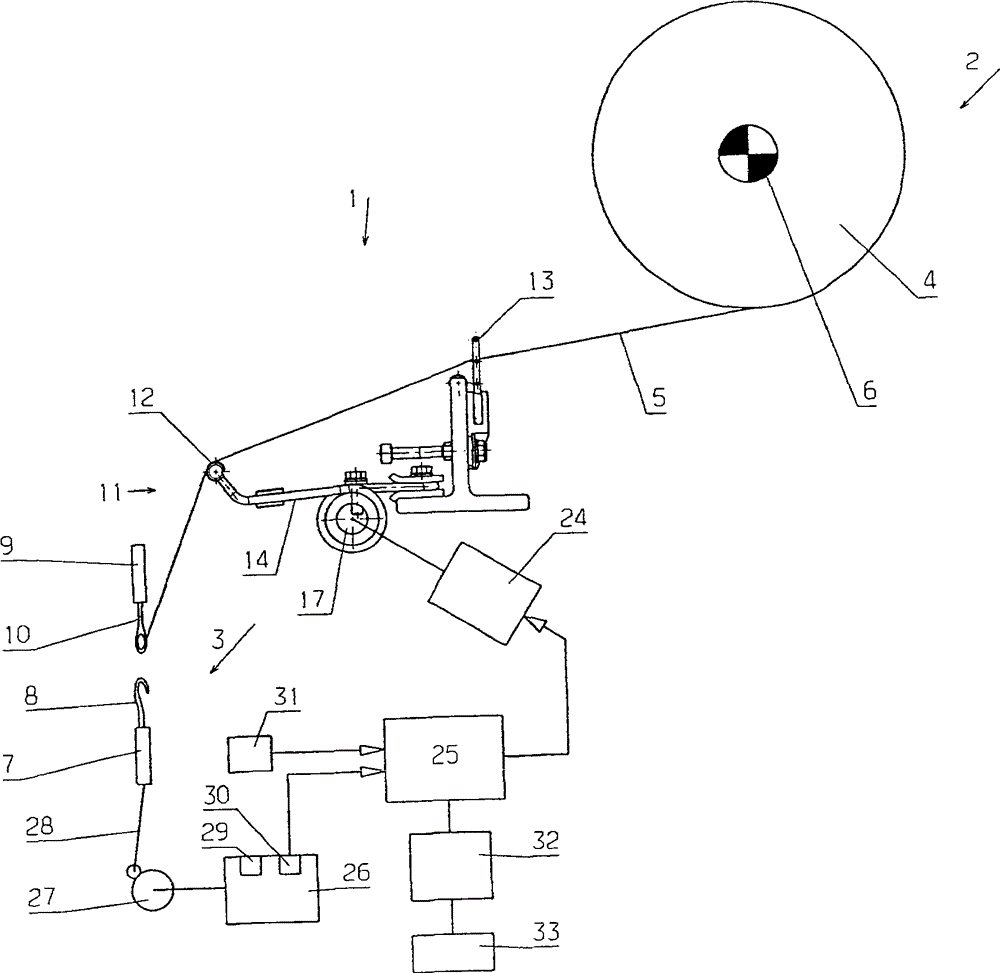
[0025] figure 1 A warp knitting machine 1 with a thread feeding zone 2 and a knitting zone 3 is shown very schematically. In this case, a warp beam 4 is arranged in the thread feed area 2 , which supplies the yarn sheets. The yarn sheet has a plurality of threads 5 arranged next to one another, one of which can be seen in the figure. Other lines are placed after it, perpendicular to the drawing plane.

[0026] The warp beam 4 is driven by the drive 6 in such a way that the thread 5 is delivered at a constant speed.

[0027] The knitting area 3 shown here in a very simplified manner has a knitting needle bar 7 on which a plurality of knitting needles 8 are arranged. The knitting needles 8 are arranged one behind the other perpendicular to the plane of the drawing, so that only one knitting needle 8 is visible. Furthermore, the knitting area 3 has a bar 9 on which a plurality of eye needles 10 are arranged. Other eye pins are located behind it perpendicular to the drawing p...


PUM


Abstract

The knitting machine (1) has a yarn feeding portion (2), an active region (3), and a thread tension compensating device (11) connected to the yarn feeding portion and the active region. The tension compensating device can be actuated from the outside through a control device (17) with which a natural frequency of the tension compensating device is varied. The tension compensating device is comprised of a spring arrangement which comprises several springs (14) distributed over the working width of knitting machine. The control device acts simultaneously on all the springs.

Description

technical field [0001] The invention relates to a warp knitting machine (Kettenwirkmaschine) with a thread feed area (Fadenlieferbereich), a knitting area (Wirkbereich) and a thread stress equalization device (Fadenspannungsausgleichseinrichtung) between the thread feed area and the knitting area. Background technique [0002] During the production of knitted fabrics, the warp threads are usually conveyed at a constant speed from the thread feed area. For this purpose, the thread supply area has, for example, a warp beam which is driven in such a way that the speed of the supplied thread is constant. However, during the knitting process itself, ie during the actual loop formation, the thread consumption is not constant, but fluctuates around a mean value, which corresponds to a constant speed. However, in order to achieve a good mesh structure and a good loop formation, a thread stress compensation device is arranged between the thread feed area and the knitting area. With...

Claims


Application Information

Patent Timeline
Patent Type & Authority Patents(China)
IPC IPC(8): D04B27/00D04B27/10
CPCD04B27/14
Inventor K·B·布兰德尔
Owner KARL MAYER STOLL R&D GMBH
Features
  • R&D
  • Intellectual Property
  • Life Sciences
  • Materials
  • Tech Scout
  • Unparalleled Data Quality
  • Higher Quality Content
  • 60% Fewer Hallucinations
Learn More