
Vibration control apparatus of wind turbine generator and wind turbine generator

a technology of vibration control apparatus and wind turbine generator, which is applied in the direction of machines/engines, shock absorbers, liquid fuel engines, etc., can solve the problems of increasing the weight of the tower is significantly increased, and the fatigue load might significantly increas

Active Publication Date: 2012-12-04
MITSUBISHI HEAVY IND LTD
View PDF22 Cites 8 Cited by
  • Summary
  • Abstract
  • Description
  • Claims
  • Application Information

AI Technical Summary

Benefits of technology

The present invention provides a vibration control apparatus for a wind turbine generator that can be installed in a small space inside a tower without increasing the weight of the tower. The apparatus includes a swinging rod, a flange part, a pendulum, and attenuation devices. The apparatus can change the natural frequency of the wind turbine generator, preventing an increase in the amplitude of vibration associated with the rotation of the wind-turbine rotary blades. The apparatus also prevents an increase in the weight of the tower when the attenuation devices are attached to the inner wall surface of the tower. The apparatus includes at least two pendular TMDs, which even if one of the devices fails, ensures control of vibration. The apparatus can be easily and quickly assembled and maintained. The wind turbine generator with the vibration control apparatus can cope with an increase in size and hub height of the wind turbine.

Problems solved by technology

However, with those that have a hub height exceeding 100 m, the first-mode natural frequency of the tower matches the resonance range associated with the rotation of the rotor head and the wind-turbine rotary blades, and thus, the fatigue load might significantly increase.
Therefore, the thickness of the tower needs to be increased so as to reduce the fatigue load applied to the tower, and thus, there is a problem in that the weight of the tower significantly increases.
Therefore, the inner wall surface of the tower has to be reinforced, and thus, there is a problem in that the weight of the tower increases.

Method used


Image

  • Vibration control apparatus of wind turbine generator and wind turbine generator
  • Vibration control apparatus of wind turbine generator and wind turbine generator
  • Vibration control apparatus of wind turbine generator and wind turbine generator

Examples


Embodiment Construction

[0038]A vibration control apparatus of a wind turbine generator according to an embodiment of the present invention will be described with reference to FIGS. 1 to 9.

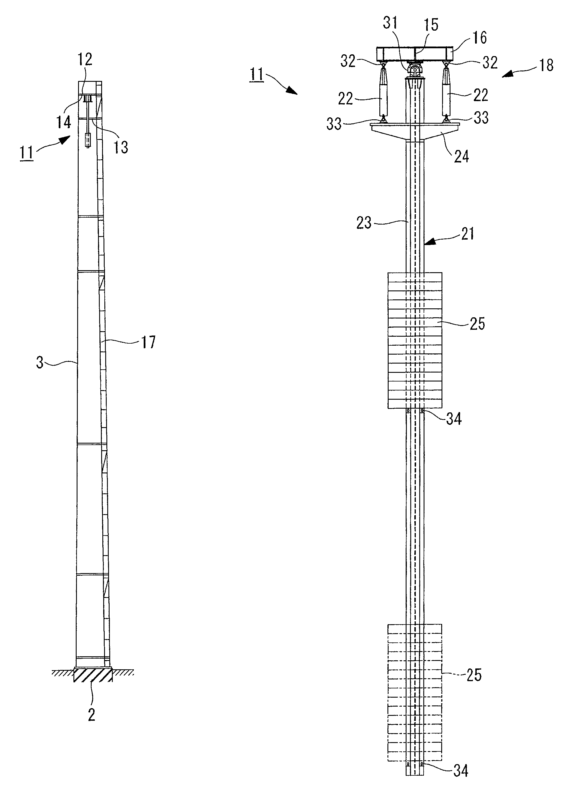
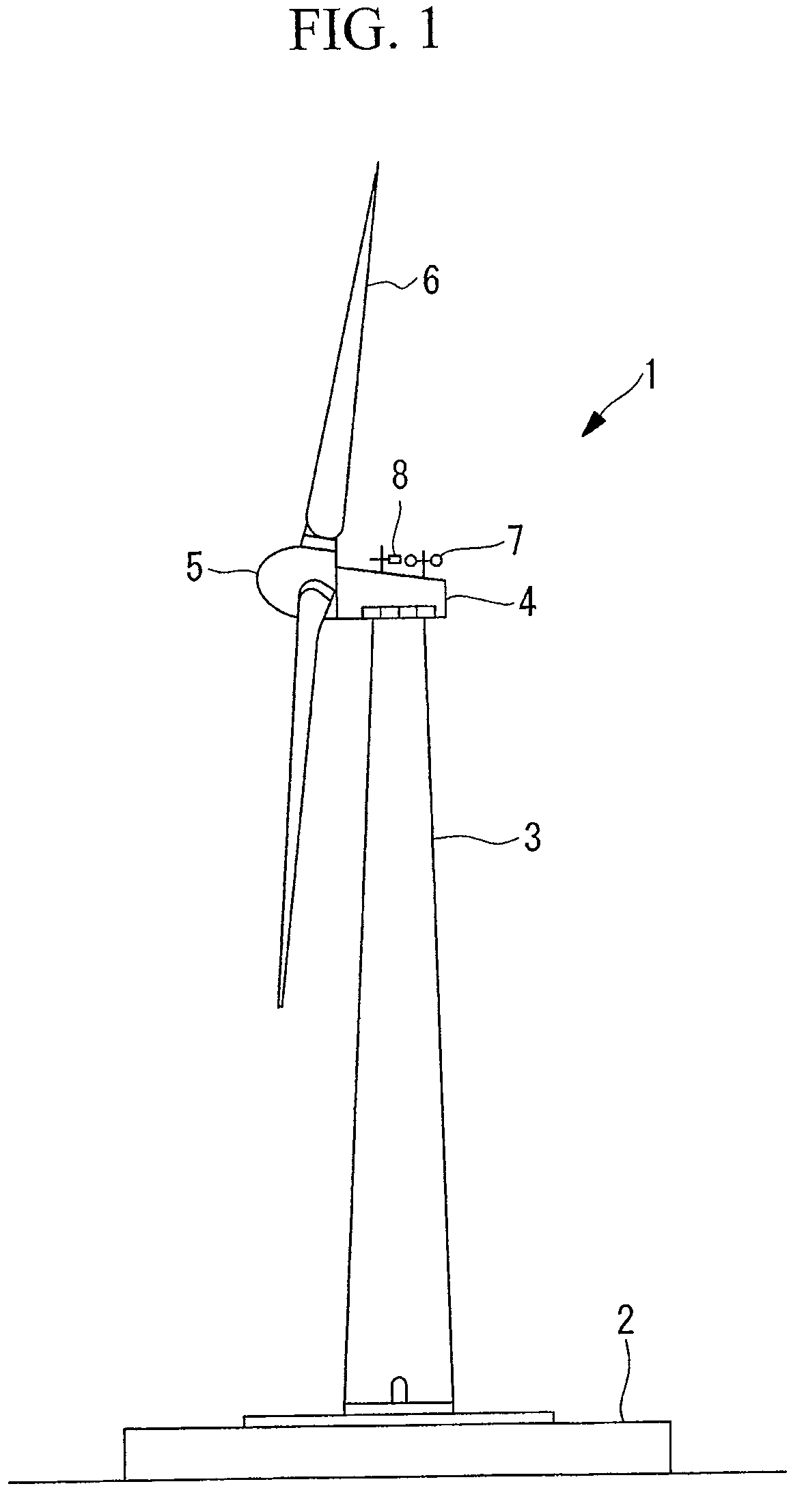
[0039]FIG. 1 is a schematic side view of a wind turbine generator including a vibration control apparatus of a wind turbine generator according to an embodiment of the present invention and, as viewed from the left of a tower; FIG. 2 is a side view of the inside of the tower of a wind turbine generator including a vibration control apparatus of a wind turbine generator according to an embodiment of the present invention, as viewed from the left of a tower; FIG. 3 illustrates the configuration of a vibration control apparatus of a wind turbine generator according to an embodiment of the present invention; FIG. 4 is a diagram illustrating an enlarged relevant portion of FIG. 3; FIG. 5 illustrates the positional relationship of a longitudinal beam and a transverse beam disposed on the lower surface of a top floor and univer...


PUM


Abstract

A vibration control apparatus of a wind turbine generator that can be installed in a small space inside a tower, without a weight increase of the tower, and that can change the natural frequency thereof is provided. Included is a swinging rod extending in the vertical direction and suspended from beams provided on an upper part of the tower via a first universal joint; a flange part extending outward from the upper end outer surface of the swinging rod in the radial direction along the circumferential direction; a pendulum including a bob attached to the swinging rod and capable of moving up and down in the vertical direction; and a plurality of attenuation devices each of whose upper end is attached to the beams with a second universal joint and whose lower end is attached to the flange part with a third universal joint.

Description

CROSS REFERENCE TO RELATED APPLICATIONS[0001]This is a continuation of International Application PCT / JP / 2010 / 073514, with an international filing date of Dec. 27, 2010, which is hereby incorporated by reference herein in its entirety.BACKGROUND OF THE INVENTION[0002]1. Field of the Invention[0003]The present invention relates to a vibration control apparatus that is suitable for application to a wind turbine generator.[0004]2. Description of Related Art[0005]Today, wind turbine generators are being made larger and larger in order to improve their power generating efficiency and to increase the amount of generated power, and ones having a hub height (height from ground to center of hub) exceeding 100 m have been designed for practical use.[0006]However, with those that have a hub height exceeding 100 m, the first-mode natural frequency of the tower matches the resonance range associated with the rotation of the rotor head and the wind-turbine rotary blades, and thus, the fatigue load...

Claims


Application Information

Patent Timeline
Patent Type & Authority Patents(United States)
IPC IPC(8): F03D11/00
CPCF03D11/00F16F7/10F05B2260/96Y02E10/726Y02E10/722F03D80/00Y02E10/728Y02E10/72F03D13/20E04H12/00F05B2240/912F05B2260/964
Inventor KAWABATA, MINORUKUBO, ATSUSHI
Owner MITSUBISHI HEAVY IND LTD
Learn More