Pod-shaped support rod throw-away deployment mechanism

A technology of deployment mechanism and support rod, which is applied in the field of spacecraft deployment, can solve the problems of restricting the application of multi-interface pod rods, uncoordinated movement of multi-point connections, etc., and achieves the effects of high deployment reliability and small folded volume.

Active Publication Date: 2018-01-26
SHANGHAI AEROSPACE SYST ENG INST
View PDF5 Cites 14 Cited by
  • Summary
  • Abstract
  • Description
  • Claims
  • Application Information

AI Technical Summary

Problems solved by technology

Due to the different trajectories of the pod rod curling motion and the film unfolding translational motion, the multi-point connection has motion inconsistency, which limits the application of the multi-interface pod rod in the film expandable structure.

Method used


Image

  • Pod-shaped support rod throw-away deployment mechanism
  • Pod-shaped support rod throw-away deployment mechanism
  • Pod-shaped support rod throw-away deployment mechanism

Examples


Embodiment Construction

[0046] The present invention will be further described in detail below through specific embodiments in conjunction with the accompanying drawings.

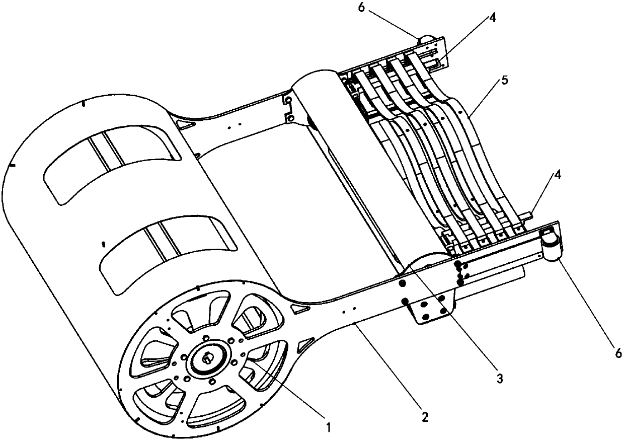
[0047] This example provides a pod-shaped support rod throwing and expanding mechanism, and its structural schematic diagram is as follows figure 1 As shown, it includes a drum assembly 1, a frame 2, a deployment drive device 3, a guide device 4, several sets of throwing devices 5 and a thrust device 6, and the drum assembly 1, deployment drive device 3 and guide device 4 are sequentially installed on the frame 2 , several groups of throwing devices 5 are sequentially slidably connected to the guide device 4, and the thrust device 6 is installed on the frame 2.

[0048] Among them, the frame 2 is the supporting structure of the whole mechanism, which provides corresponding installation interfaces for each functional component, and the roller assembly 1 is used to connect and fix the end face of the pod-shaped support rod 7, and ro...


PUM


Abstract

A pod-shaped support rod throw-away deployment mechanism includes a roller assembly, a frame, a deployment drive device, guide devices, a plurality of groups of throw-away devices and thrust devices.The roller assembly, the deployment drive device and the guide devices are sequentially arranged on the frame. The plurality of groups of throw-away devices are sequentially slidably connected to theguide devices. The thrust devices are mounted on the frame. A pod-shaped support rod is wound on the roller assembly. The deployment drive device drives the pod-shaped support rod to extend to the outer side of the frame. When the throw-away devices are squeezed by the guide devices, the throw-away devices reach the face of the pod-shaped support rod. When the pod-shaped support rod is moved froma predetermined specific position to below the throw-away devices, the throw-away devices are locked to the pod-shaped support rod and moves with the pod-shaped support rod to the outer side of the frame until the throw-away devices are detached from the frame. Through the plurality of groups of throw-away devices and the pod-shaped supporting rod, the pod-shaped supporting rod can have a multi-point connection capability.

Description

technical field [0001] The invention relates to the technical field of spacecraft deployment, in particular to a pod-shaped support rod throwing and deployment mechanism. Background technique [0002] The spacecraft deployment technology is a key technology for large-scale space structures to achieve reliable deployment and shape retention in orbit, so as to have the ability to perform missions. With the development of large-scale, lightweight and high-precision space deployable structures, elastic deployable structures are more and more used in the deployment and support of aerospace structures. Typical applications are flexible solar cell arrays, solar sails, space Antennas, hoods, etc. The elastic expandable structure is an elastic energy storage type expandable structure. It relies on its own large-strain bending deformation and high-precision springback to realize the structure's collapse and expansion. It has the advantages of light weight, good rigidity, small storag...

Claims


Application Information

Patent Timeline
Patent Type & Authority Applications(China)
IPC IPC(8): B64G1/22
Inventor 谢超彭福军秦礼王滢红张良俊
Owner SHANGHAI AEROSPACE SYST ENG INST
Why Eureka
Try Eureka