Supercharge Your Innovation With Domain-Expert AI Agents!

Methods and circuitry for driving display devices

A display device, drive circuit technology, applied in the direction of static indicators, instruments, etc.

Active Publication Date: 2018-01-26
E INK CORPORATION
View PDF184 Cites 0 Cited by
  • Summary
  • Abstract
  • Description
  • Claims
  • Application Information

AI Technical Summary

Problems solved by technology

For large displays, a large number of such local drivers are required and the drivers must be mounted and wired individually

Method used


Image

  • Methods and circuitry for driving display devices
  • Methods and circuitry for driving display devices
  • Methods and circuitry for driving display devices

Examples


Embodiment Construction

[0022] The term "electro-optic" as applied to materials or displays is used herein in its conventional meaning in the field of imaging to refer to materials having first and second display states that differ in at least one optical property, obtained by applying an electric field to Material to change the material from its first display state to its second display state. While an optical property is generally color perceived by the human eye, it can be another optical property such as light transmission, reflectivity, fluorescence, or in the case of displays intended for machine reading, electromagnetic waves outside the range of visible light False color in the sense of long reflectivity changes.

[0023] The term "gray state" is used herein in its conventional meaning in the imaging field to refer to a state intermediate between two extreme optical states of a pixel, and does not necessarily imply a black-and-white transition between these two extreme states. For example, s...


PUM


Abstract

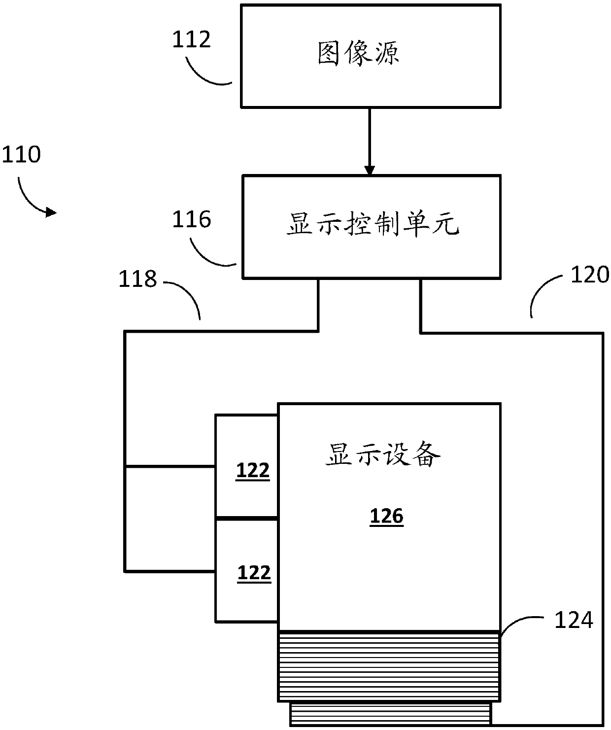
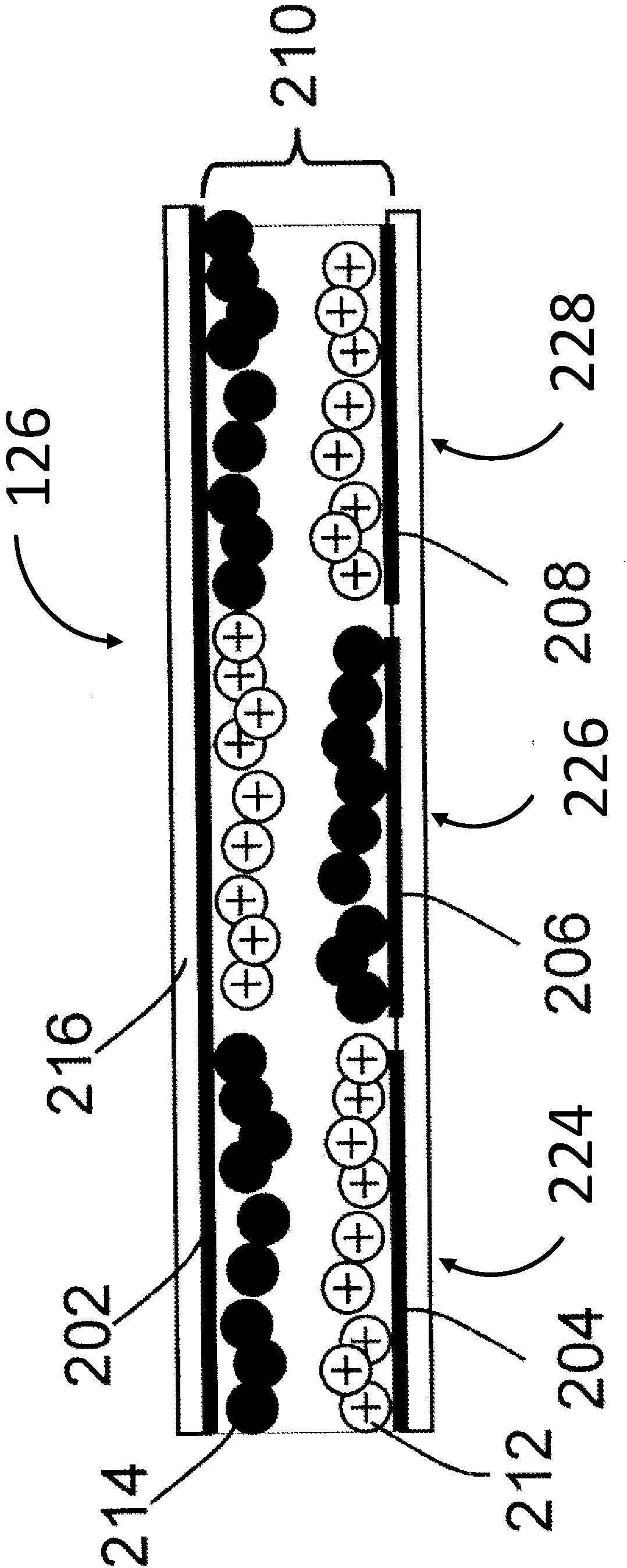
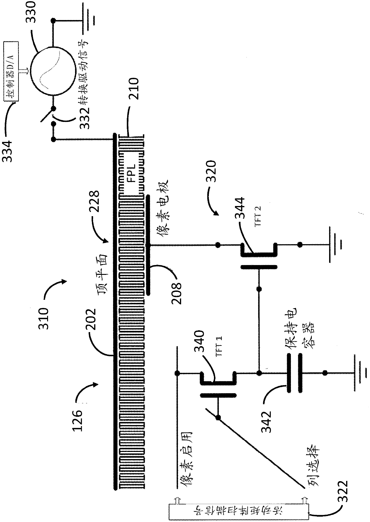
A display device is operated by using several iterations of a scan phase followed by a global drive phase. In the scan phase, the state of each pixel in the display device is set to either "enabled" or "disabled", during which time a global drive generator is inactive. Then, in the global drive phase, a global drive signal is sent to the display device. Only the subset of enabled pixels is affected by the global drive signal, which causes the enabled pixels to perform a transition to a desired display state. The sequence of the scan phase followed by the global drive phase is then repeated upto the number of unique transitions required to update the display device.

Description

[0001] References to related applications [0002] This application is related to US provisional application 62 / 167,065, filed May 27, 2015. technical field [0003] The present disclosure relates to electro-optic devices and methods, and more particularly to methods and circuits for driving electro-optic displays. Background technique [0004] Signage is an emerging application for electro-optic displays. Compared to common electro-optic displays such as those used in portable readers and other display devices, such signs are often characterized by large size and relatively infrequent updates of the displayed information. Techniques for driving such displays include tiled active matrix and direct drive on the backside of the printed circuit board of the display device. Both methods have disadvantages. [0005] Due to the large pixel count of such display devices, the active matrix approach requires high frequency drivers, which are expensive and consume a lot of power. ...

Claims


Application Information

Patent Timeline
IPC IPC(8): G09G3/34
CPCG09G3/344G09G2310/0251G09G2300/0842G09G2310/063
Inventor K·R·可劳恩斯
Owner E INK CORPORATION
Features
  • R&D
  • Intellectual Property
  • Life Sciences
  • Materials
  • Tech Scout
  • Unparalleled Data Quality
  • Higher Quality Content
  • 60% Fewer Hallucinations
Learn More