
A shoe-making robot
A robot and fuselage technology, applied in shoemaking machinery, beating machines, footwear, etc., can solve the problems of difficulty in controlling the movement and handling of machinery manually, easily hurting the hands of operators, time-consuming and labor-intensive problems, etc., to improve accuracy As well as the effects of stability, labor intensity reduction and convenient operation
- Summary
- Abstract
- Description
- Claims
- Application Information
AI Technical Summary
Problems solved by technology
Method used
Image


Examples
Embodiment Construction
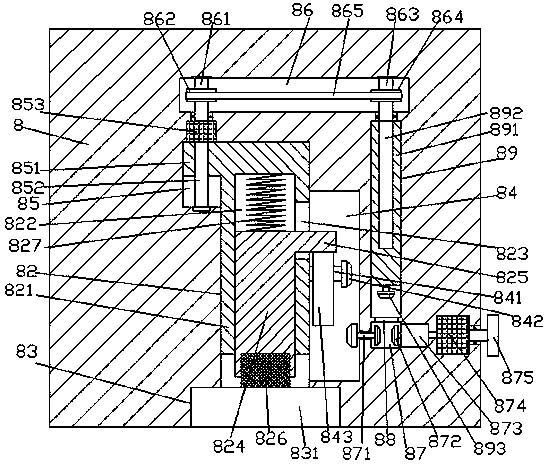
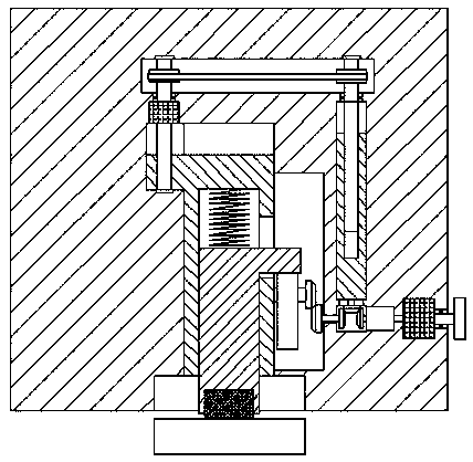
[0019] Such as Figure 1-Figure 4 As shown, a shoe-making robot of the present invention includes a fuselage 8 and a rolling wheel 81 that is arranged on the bottom of the fuselage 8. A sinking groove 83 is provided in the bottom surface of the fuselage 8, and the sinking connection The top wall of the groove 83 is penetrated with a lift-off and landing sliding joint groove 82 extending upwards. The fuselage 8 above the lifting and landing sliding joint groove 82 is provided with a first transfer chamber 86 extending left and right. A second transfer cavity 84 is formed in the inner wall of the right side of the lifting and lowering sliding connection groove 82, and a first guiding groove 85 is formed in the top of the left inner wall of the lifting and lowering sliding connecting groove 82, and the top of the first guiding groove 85 Opposite to the bottom of the extension tail on the left side of the first transfer cavity 86, the first guide groove 85 is provided with a first...
PUM
 Abstract
Description
Claims
Application Information