
Stable shoemaking robot

A robot and stable technology, applied in shoe-making machinery, beating machines, footwear, etc., can solve problems such as difficulty in manual control of mechanical movement and removal, easy injury and operator's hands, time-consuming and labor-intensive, etc., to improve accuracy and The effect of stability, reducing labor intensity and convenient operation

Inactive Publication Date: 2018-05-25
何慧敏
View PDF0 Cites 0 Cited by
  • Summary
  • Abstract
  • Description
  • Claims
  • Application Information

AI Technical Summary

Problems solved by technology

The traditional hammer leveling method uses a manual hand-held hammer head for hammering, which is easy to hurt the hands of the operator, and is inefficient, time-consuming, laborious, slow, and it is difficult to control the movement and handling of the machine manually.

Method used


Image

  • Stable shoemaking robot
  • Stable shoemaking robot
  • Stable shoemaking robot

Examples


Embodiment Construction

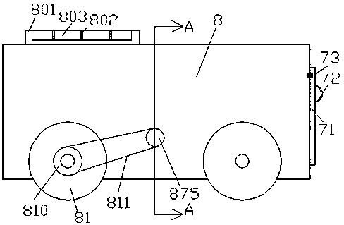
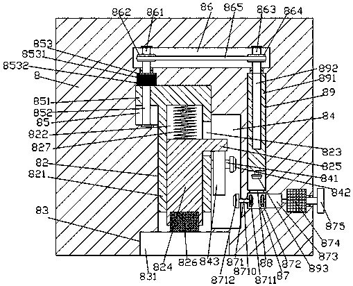
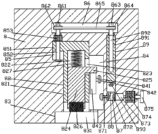
[0020] Such as Figure 1-Figure 4 As shown, a stable shoe-making robot of the present invention includes a fuselage 8 and a rolling wheel 81 that is arranged on the bottom of the fuselage 8, and a sinking groove 83 is provided in the bottom surface of the fuselage 8. The upper wall of the sinking groove 83 is penetrated with a take-off and landing sliding connection groove 82 extending upwards. The fuselage 8 above the lifting and landing sliding connection groove 82 is provided with a first transfer chamber 86 extending left and right. A second transfer cavity 84 is formed in the inner wall on the right side of the lift-off and landing sliding joint groove 82, and a first guide groove 85 is formed in the top of the left inner wall of the lift-off and landing sliding joint groove 82. The first guide groove The top of 85 is opposite to the bottom of the extension tail tip on the left side of the first transfer chamber 86. The first guide groove 85 is provided with a first screw...


PUM


Abstract

The invention discloses a stable shoemaking robot. The robot comprises a machine body and rolling wheels arranged at the bottom of the machine body, and a sunken receiving tank is arranged in the bottom face of the machine body; a take-off and landing sliding connection groove which extends upwards runs through the inner top wall of the sunken receiving tank, and a first transmission cavity whichis formed in a left-right extending mode is formed in the position, above the take-off and landing sliding connection groove, of the machine body; a second transmission cavity runs through the inner wall of the right side of the take-off and landing sliding connection groove, a first guide groove runs through the top of the left inner wall of the take-off and landing sliding connection groove, thetop of the first guide groove is opposite to the bottom of the tail extending end of the left side of the first transmission cavity, and a first screw rod which extends up and down is arranged in thefirst guide groove; the tail extending end of the top of the first screw rod is in matched connection with a first driver, and the outer surface of the first driver is arranged in the inner top wallof the first guide groove and is fixedly connected with the inner top wall. The robot is simple in structure and convenient to operate, the accuracy and stability of hammering are improved, the laborintensity of workers is reduced, and the transportation cost is reduced.

Description

technical field [0001] The invention relates to the field of shoemaking, in particular to a stable shoemaking robot. Background technique [0002] After the shoe upper is cut and sealed, it is necessary to further hammer and trim the uneven seam of the heel and the thick hem, so that the shoe mouth, the hem or the joint of the upper are smooth and beautiful. The traditional hammer leveling method uses a manual hand-held hammer head for hammering, which is easy to hurt the hands of the operator, and is inefficient, time-consuming, laborious, slow, and it is difficult for humans to control the mechanical movement and handling. Contents of the invention [0003] The technical problem to be solved by the present invention is to provide a stable shoe-making robot, which can solve the above-mentioned problems in the prior art. [0004] The present invention is achieved through the following technical solutions: a stable shoe-making robot of the present invention includes a fuse...

Claims


Application Information

Patent Timeline
Patent Type & Authority Applications(China)
IPC IPC(8): A43D49/00
CPCA43D49/00
Inventor 何慧敏
Owner 何慧敏
Learn More