
Television cabinet structure for non-screen television

A technology for screenless TVs and TV cabinets, applied in applications, cabinets, home appliances, etc., can solve the problems of unconsidered projection, inappropriate distance, inconvenient use, etc., to achieve convenient viewing, strong practicability, and improve overall aesthetics Effect

Inactive Publication Date: 2018-01-30
CHENGDU 90 DEGREE IND PROD DESIGN CO LTD
View PDF0 Cites 0 Cited by
  • Summary
  • Abstract
  • Description
  • Claims
  • Application Information

AI Technical Summary

Problems solved by technology

[0003] However, there are many inconveniences in the application and promotion of screenless TVs. Because screenless TVs need to place an ultra-short-throw projector under the hard screen, and then watch them by projecting the ultra-short-throw projector onto the hard screen, it is necessary The distance between the TV cabinet and the hard screen must be very appropriate, and most of the existing TV cabinets are only used to store items, without considering the problem of projection. Therefore, when placing an ultra-short-throw projector on the existing TV cabinet, It is often necessary to move the TV cabinet due to the inappropriate distance. At the same time, when the ultra-short-throw projector needs to be stored after watching, it is very inconvenient to use. Therefore, it is necessary to develop A TV cabinet specially used for screenless TV

Method used


Image

  • Television cabinet structure for non-screen television
  • Television cabinet structure for non-screen television
  • Television cabinet structure for non-screen television

Examples


Embodiment approach

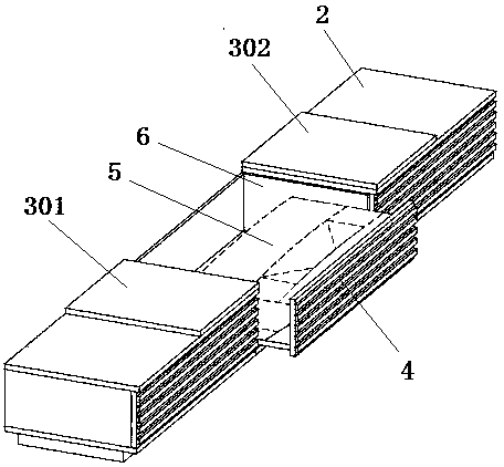
[0023] As an embodiment, the flip board 3 includes a board A 301 and a board B 302, the board A 301 is side by side with the board B 302, the side of the board A 301 away from the board B 302 is rotationally connected with the TV cabinet 2, and the board B 302 is away from the board A One side of 301 is rotationally connected with TV cabinet 2, as image 3 shown. When overturning, the overturning plate 3 is overturned towards both sides of the TV cabinet 2, so that the upper end surface of the drawer 4 can be opened. Furthermore, both the board A 301 and the board B 302 can rotate 180° relative to the TV cabinet 2 . When turned over, the turning board 3 can be stacked on the TV cabinet 2, further reducing the influence of the turning board 3 on the projection of the projector 5.

[0024] As an alternative embodiment, the flip board 3 includes a board A 301 and a board B 302, the board A 301 and the board B 302 are side by side, and the side of the board A 301 away from the b...


PUM


Abstract

The invention discloses a television cabinet structure for a non-screen television. The television cabinet structure comprises a television cabinet arranged on the lower portion of a hard screen, a cabinet body for containing a projector is arranged in the middle of the television cabinet and comprises a turnover plate and a drawer, the turnover plate is arranged on the upper end face of the television cabinet, the drawer is slidably connected with the television cabinet, the projector is placed in the drawer, the turnover plate covers the upper end face of the drawer and is flush with the upper end face of the television cabinet, one side of the turnover plate is rotatably connected with the television cabinet, and the turnover plate can freely turn over up and down to open / close the upper end face of the drawer. According to the television cabinet structure for the non-screen television, large structural change of an existing television cabinet is omitted, and the structure solves the problems that a projection area is easily shielded, the projector is inconveniently stored and the like by the aid of the drawer and the turnover plate. Besides, by the aid of the turnover plate, overall attractiveness of the television cabinet is improved, stacking of articles on the television cabinet cannot be affected, and the structure is strong in practicability.

Description

technical field [0001] The invention relates to the field of screenless television equipment, in particular to a television cabinet structure for a screenless television. Background technique [0002] Compared with TV, screenless TV can realize the same signal input picture and sound as TV. The difference between the two lies in the principle of imaging. Ordinary TVs use LED light to shine on the LCD screen to form images, while screenless TVs use light sources to reflect on the hard screen to form images. The advantage of screenless TV is that the screen size can be adjusted, and the mobile installation is convenient. At present, according to different light sources and places of use, it can be divided into laser screenless TVs, living room screenless TVs and portable screenless TVs. Laser screenless TV adopts the ultra-short-focus projection principle and is equipped with a laser light source. It is mostly used in living rooms or meeting rooms. The living room screenless...

Claims


Application Information

Patent Timeline
Patent Type & Authority Applications(China)
IPC IPC(8): A47B81/06A47B88/40A47B96/20A47B97/00
Inventor 卢晔
Owner CHENGDU 90 DEGREE IND PROD DESIGN CO LTD
Learn More