
A concealed hinge for furniture

A technology for concealed hinges and furniture, which can be used in hinges with pins, buildings, door/window accessories, etc. It can solve the problems of difficult alloy castings and upper adjustment plate riveting reliability, high manufacturing and maintenance costs, hidden dangers in hinge quality, etc. to reduce the risk of subsidence, facilitate installation and use, and improve connection stability

Active Publication Date: 2019-09-24
江西美达教育设备集团有限公司
View PDF1 Cites 0 Cited by
  • Summary
  • Abstract
  • Description
  • Claims
  • Application Information

AI Technical Summary

Problems solved by technology

[0002] Chinese Patent Document No. CN2780937Y disclosed on May 17, 2006 a hidden hinge for furniture doors that can be adjusted in three dimensions. It includes a movable base that can be fixed on the door body, an adjustable base that can be fixed on the door frame and a connecting The rotating arm in between, wherein the adjustable base includes a bottom plate that can be fixed on the door frame, a middle plate that slides up and down on the bottom plate, and an upper adjustment plate that slides back and forth on the middle plate. Laminate structure, in which the plate is formed by alloy casting and then secondly extruded and riveted with the lower adjustment plate. Although the production process is simple, this process has hidden dangers to the quality of the hinge. After the alloy casting is extruded twice The internal structure of the material changes, such as looseness, cracking, etc., so it is difficult to ensure the reliability of the riveting between the alloy casting and the upper adjustment plate, resulting in a low strength of the hinge, and the door panel is easy to fall, and the service life is short , and the structure is complex, there are many assembly parts, and the manufacturing and maintenance costs are high

Method used


Image

  • A concealed hinge for furniture
  • A concealed hinge for furniture
  • A concealed hinge for furniture

Examples


Embodiment Construction

[0013] The following will clearly and completely describe the technical solutions in the embodiments of the present invention with reference to the accompanying drawings in the embodiments of the present invention. Obviously, the described embodiments are only some of the embodiments of the present invention, not all of them. Based on the embodiments of the present invention, all other embodiments obtained by persons of ordinary skill in the art without making creative efforts belong to the protection scope of the present invention.

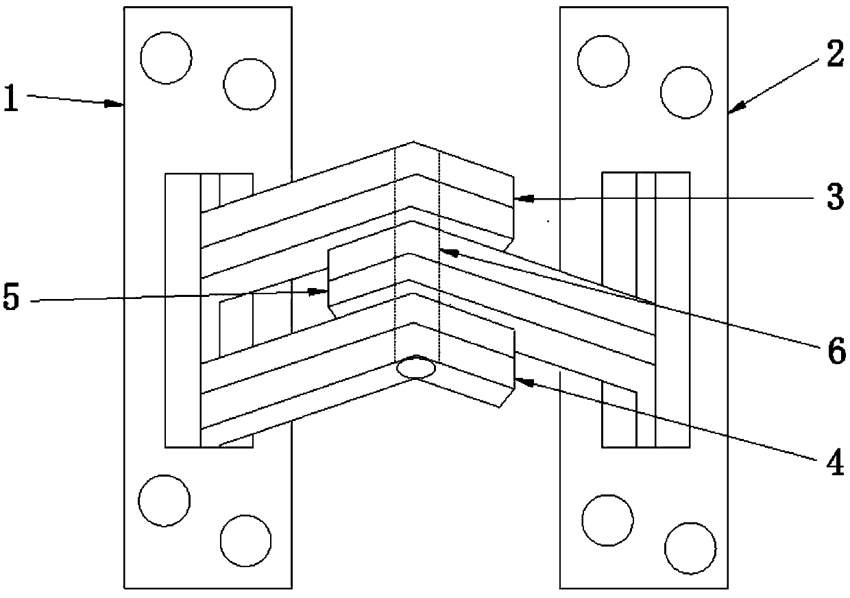
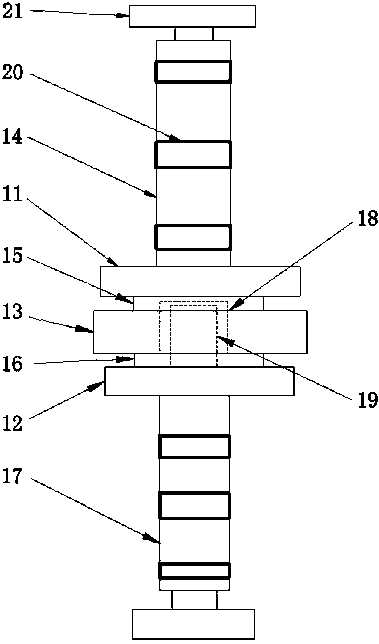
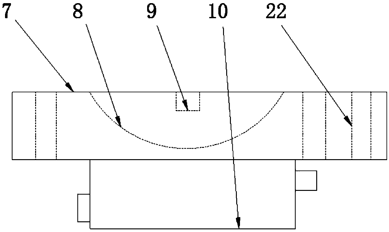
[0014] see Figure 1-3 , the present invention provides a technical solution: a concealed hinge for furniture, including a first base 1, a second base 2, a first connecting arm 3, a second connecting arm 4, a third connecting arm 5 and a rotating shaft 6, The first base 1 and the second base 2 are arranged in parallel, and the structure of the first base 1 and the second base 2 is exactly the same, including the bottom plate 7, the top of the bot...


PUM


Abstract

The invention discloses a concealed hinge for furniture. The concealed hinge comprises a first base, a second base, a first connecting arm, a second connecting arm, a third connecting arm and a rotating shaft, and the first base and the second base are parallelly arranged; the structure of the first base is fully consistent with that of the second base, each base comprises a bottom plate, the topof each bottom plate is provided with a clamping groove and a supporting rod; the supporting rods are arranged in the clamping grooves, a supporting frame is arranged at the bottom of each bottom plate, and the first connecting arm, the second connecting arm and the third connecting arm are of fully same structure and are in an L shape; the head parts of the first connecting arm and the second connecting arm are fixedly connected with the first base, the head part of the third connecting arm is fixedly connected with the second base, and a passing and penetrating hole is formed in the third connecting arm; and a rotating shaft penetrates through and is inserted in the passing and penetrating hole, the top of the rotating shaft is fixedly connected with the first connecting arm, and the bottom of the rotating shaft is fixedly connected with the second connecting arm. The concealed hinge for the furniture is simple in structure and convenient to mount and can effectively deal with different furniture needs, and smooth opening and closing are ensured.

Description

technical field [0001] The invention relates to the technical field of furniture appliances, in particular to a concealed hinge for furniture. Background technique [0002] Chinese Patent Document No. CN2780937Y disclosed on May 17, 2006 a hidden hinge for furniture doors that can be adjusted in three dimensions. It includes a movable base that can be fixed on the door body, an adjustable base that can be fixed on the door frame and a connecting The rotating arm in between, wherein the adjustable base includes a bottom plate that can be fixed on the door frame, a middle plate that slides up and down on the bottom plate, and an upper adjustment plate that slides back and forth on the middle plate. Laminate structure, in which the plate is formed by alloy casting and then secondly extruded and riveted with the lower adjustment plate. Although the production process is simple, this process has hidden dangers to the quality of the hinge. After the alloy casting is extruded twice...

Claims


Application Information

Patent Timeline
Patent Type & Authority Patents(China)
IPC IPC(8): E05D3/02E05D5/02
Inventor 刘靖
Owner 江西美达教育设备集团有限公司
Learn More