Solution floating ball valve device

A float valve and solution technology, applied in the direction of valve device, valve operation/release device, lift valve, etc., can solve the problems of inaccurate adjustment and unstable operation of the float valve, so as to prolong the service life of the pump, reduce the area, Obvious effect

Inactive Publication Date: 2018-02-02
TONGFANG KAWASAKI ADVANCED ENERGY SAVING MACHINE
View PDF5 Cites 2 Cited by
  • Summary
  • Abstract
  • Description
  • Claims
  • Application Information

AI Technical Summary

Problems solved by technology

[0003] The purpose of the present invention is to provide a solution float valve device to solve the problems of unstable operation and inaccurate adjustment of the existing float valve

Method used


Image

  • Solution floating ball valve device

Examples


Embodiment Construction

[0013] The following will clearly and completely describe the technical solutions in the embodiments of the present invention with reference to the accompanying drawings in the embodiments of the present invention. Obviously, the described embodiments are only some, not all, embodiments of the present invention. Based on the embodiments of the present invention, all other embodiments obtained by persons of ordinary skill in the art without making creative efforts belong to the protection scope of the present invention.

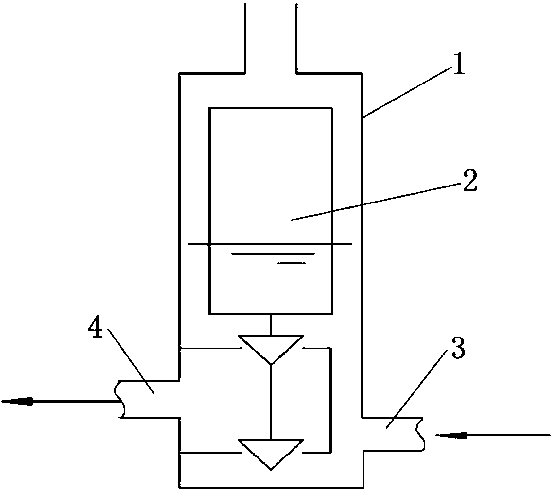
[0014] Such as figure 1 As shown, the present invention provides a solution float valve device, comprising an overflow pipe 1 and a float valve spool 2, the spool 2 is arranged in the overflow pipe 1, and an overflow port is arranged at the upper end of the overflow pipe 1, A liquid inlet 3 and a liquid outlet 4 are respectively provided on both sides below the overflow pipe 1 . In this embodiment, the valve core 2 is cylindrical. According to detailed calcu...


PUM


Abstract

The invention provides a solution floating ball valve device. The solution floating ball valve device comprises an overflow pipe and a floating ball valve core, wherein the valve core is arranged in the overflow pipe; and a solution inlet and a solution outlet are correspondingly formed in both sides of the lower portion of the overflow pipe. According to the solution floating ball valve device, the weight and the opening degree of the valve core are determined through the detailedly-calculated liquid level of the solution cycle during the normal operation of a unit, so that the pressure difference balance between a high temperature generator and the solution inlet in the solution floating ball valve device is guaranteed. The solution floating ball valve device can adjust the solution circulating quantity in real time so as to steplessly adjust the solution liquid level, so that the effect of energy saving is achieved.

Description

technical field [0001] The invention relates to a float valve, in particular to a solution float valve device. Background technique [0002] There are two ways to adjust the liquid level of the traditional solution circulation: 1 is manual valve adjustment, and 2 is the liquid level electrode plus frequency conversion pump adjustment. The disadvantage is that the manual valve adjustment cannot guarantee the stable and real-time adjustment of the liquid level during the automatic operation of the unit. The adjustment of the liquid level electrode plus the frequency conversion pump is prone to false alarms, which will affect the normal operation of the unit. Contents of the invention [0003] The object of the present invention is to provide a solution float valve device to solve the problems of unstable operation and inaccurate adjustment of the existing float valve. [0004] The present invention is achieved in the following way: a solution float valve device, which incl...

Claims


Application Information

Patent Timeline
Patent Type & Authority Applications(China)
IPC IPC(8): F16K31/20F16K1/44
CPCF16K31/20F16K1/44
Inventor 官青山黄金龙张卫东康益军孙涛
Owner TONGFANG KAWASAKI ADVANCED ENERGY SAVING MACHINE
Why Eureka
Try Eureka