Heatdissipation dust cover for transformer and working method thereof

A working method and technology of a dust cover, applied in the field of transformers, can solve problems such as limitations of applicability and practicability, affecting heat dissipation performance, easily damaging transformers, etc., and achieving the effects of ensuring stable and reliable connection, simple operation and good practicability

Inactive Publication Date: 2018-02-06
卞毓平
View PDF6 Cites 0 Cited by
  • Summary
  • Abstract
  • Description
  • Claims
  • Application Information

AI Technical Summary

Problems solved by technology

[0002] With the maturity of my country's electric power technology, various electric power equipment develops rapidly. Power transformer is a common structure, which is mainly installed outdoors. Invasion, the traditional technology mainly uses heat dissipation windows to dissipate heat, but its waterproofness is limited. At the same time, when

Method used


Image

  • Heatdissipation dust cover for transformer and working method thereof

Examples


Embodiment 1

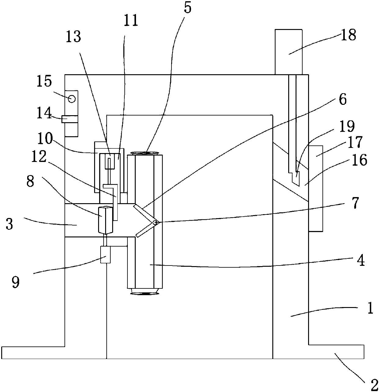
[0019] Such as figure 1 The heat dissipation and dustproof cover for the transformer shown includes a cover body 1, on which the mounting and fixing lugs 2 are arranged, and on the side wall of the cover body 1, a cooling hole 3 is arranged, and in the The cover body 1 is provided with a T-shaped air guide pipe 4, the vertical pipe of the T-shaped air guide pipe 4 communicates with the heat dissipation hole 3, and is provided at both ends of the horizontal pipe of the T-shaped air guide pipe 4. There is a cooling fan 5, and a baffle plate 6 is arranged at the center of the horizontal tube of the T-shaped air guide pipe 4, and the top of the baffle plate 6 is connected to the horizontal tube of the T-shaped air guide tube 4 by a rotating shaft 7 and the The bottom end of the baffle plate 6 is movable under the action of two heat dissipation fans 5 and is located on both sides of the vertical pipe opening of the T-shaped air guide pipe 4. At least two baffles are arranged on the...

Embodiment 2

[0025] During work, based on the structural basis of Embodiment 1, the following steps are included: the heat dissipation fan 5 at one end of the T-shaped air guide pipe 4 and the horizontal pipe works, the cold air enters the cover body 1 from the air inlet channel 16, and the baffle plate 6 is moved along the rotation axis 7. Rotate; the hot air is discharged from the cooling holes 3; the switching switch 14 switches the operation of the cooling fan 5 at the other end of the T-shaped air guide pipe 4 horizontal tube, repeats the above process, and realizes that the two cooling fans 5 work alternately. At the same time, the dust removal fan 18 works, and the cold air blows and removes dust through the tuyere 19, effectively ensuring the cleanliness of the cold air. In addition, the small motor 9 works, and the main shaft of the small motor 9 drives the dust shield 8 to rotate to keep out dust. Simultaneously, the telescopic cylinder 13 expands and contracts up and down, and d...


PUM


Abstract

The invention discloses a heatdissipation dust cover for a transformer and a working method thereof. The dust cover comprises a cover body. Mounting fixed lugs are arranged and installed on the coverbody, a heatdissipation hole is formed in the sidewall of the cover body, and a T-shaped air guide pipe is arranged in the cover body. The vertical pipe of the T-shaped air guide pipe is communicatedwith the heatdissipation hole. Heatdissipation fansare arranged at both ends of the cross pipe of the T-shaped air guide pipe, baffles are arrangedin the center of the cross pipe of the T-shaped air guide pipe, and the tops of the bafflesare connected to the cross pipe of the T-shaped air guide pipe through a rotating shaft. At least two dust-proof plates are arranged on the inner wall of the vertical cylinder of the T-shaped air guide pipe,a small motor is arranged on the outer wall of the T-shaped air guide pipe, and the spindle of the small motor passes through the side wall of the T-shapedair guide pipe and is connected with the dust-proof plates. Theheatdissipation dust cover for the transformer has a reasonablestructure, can not only improve the heat dissipation performance, but also effectively prevent dust from entering into the cover body from a heatdissipation passage; meanwhile,the heatdissipation dust cover for the transformer has good waterproof performance, good stability, good applicability and good practicality.

Description

technical field [0001] The invention belongs to the technical field of transformers, and in particular relates to a heat dissipation dust cover for a transformer and a working method of the heat dissipation dust cover for a transformer. Background technique [0002] With the maturity of my country's electric power technology, various electric power equipment develops rapidly. Power transformer is a common structure, which is mainly installed outdoors. Invasion, the traditional technology mainly uses heat dissipation windows to dissipate heat, but its waterproofness is limited. At the same time, when used for a long time, the heat dissipation windows will absorb a lot of dust, which will also affect the heat dissipation performance. Therefore, manual cleaning is required at regular intervals, which is not only time-consuming and laborious, but also It is also easy to damage the transformer, so the applicability and practicality are limited. Contents of the invention [0003]...

Claims


Application Information

Patent Timeline
IPC IPC(8): H01F27/02H01F27/08H01F27/40
CPCH01F27/02H01F27/025H01F27/085H01F27/40
Inventor 卞毓平
Owner 卞毓平
Why Eureka
Try Eureka