
Conical locking type strain clamp convenient for maintenance

A tension clamp, tapered technology, applied in the field of tapered locking tension clamp, can solve the problems of strain clamp breakage, lower power supply reliability, increased resistance, etc., to achieve structural stability and reduce power supply The effect of reliability, easy disassembly and maintenance

Active Publication Date: 2018-02-09
LISHUI POWER SUPPLY COMPANY OF STATE GRID ZHEJIANG ELECTRIC POWER +2
View PDF4 Cites 6 Cited by
  • Summary
  • Abstract
  • Description
  • Claims
  • Application Information

AI Technical Summary

Problems solved by technology

The upper drainage part of the drainage body and the jumper drainage part are connected by bolts. Although this connection structure is convenient for maintenance and replacement, it is easy to connect the bolted upper drainage part and the jumper drainage part during the long-term use of the power line. Looseness occurs, and once there is looseness between the upper drainage piece and the jumper drainage piece, the resistance between the upper drainage piece and the jumper drainage piece will increase, causing the drainage body to heat up; after the drainage body heats up, it will It will further increase the resistance between the drainage body and the clamp body, resulting in a vicious circle, seriously affecting the service life of the tension clamp, and even breaking the tension clamp, reducing the reliability of power supply

Method used


Image

  • Conical locking type strain clamp convenient for maintenance
  • Conical locking type strain clamp convenient for maintenance
  • Conical locking type strain clamp convenient for maintenance

Examples


Embodiment Construction

[0028] Below in conjunction with accompanying drawing and specific embodiment the present invention is described in further detail:

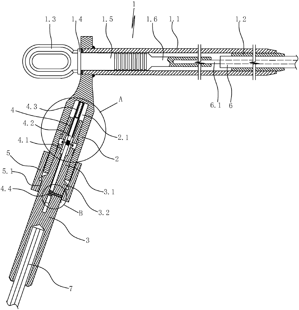
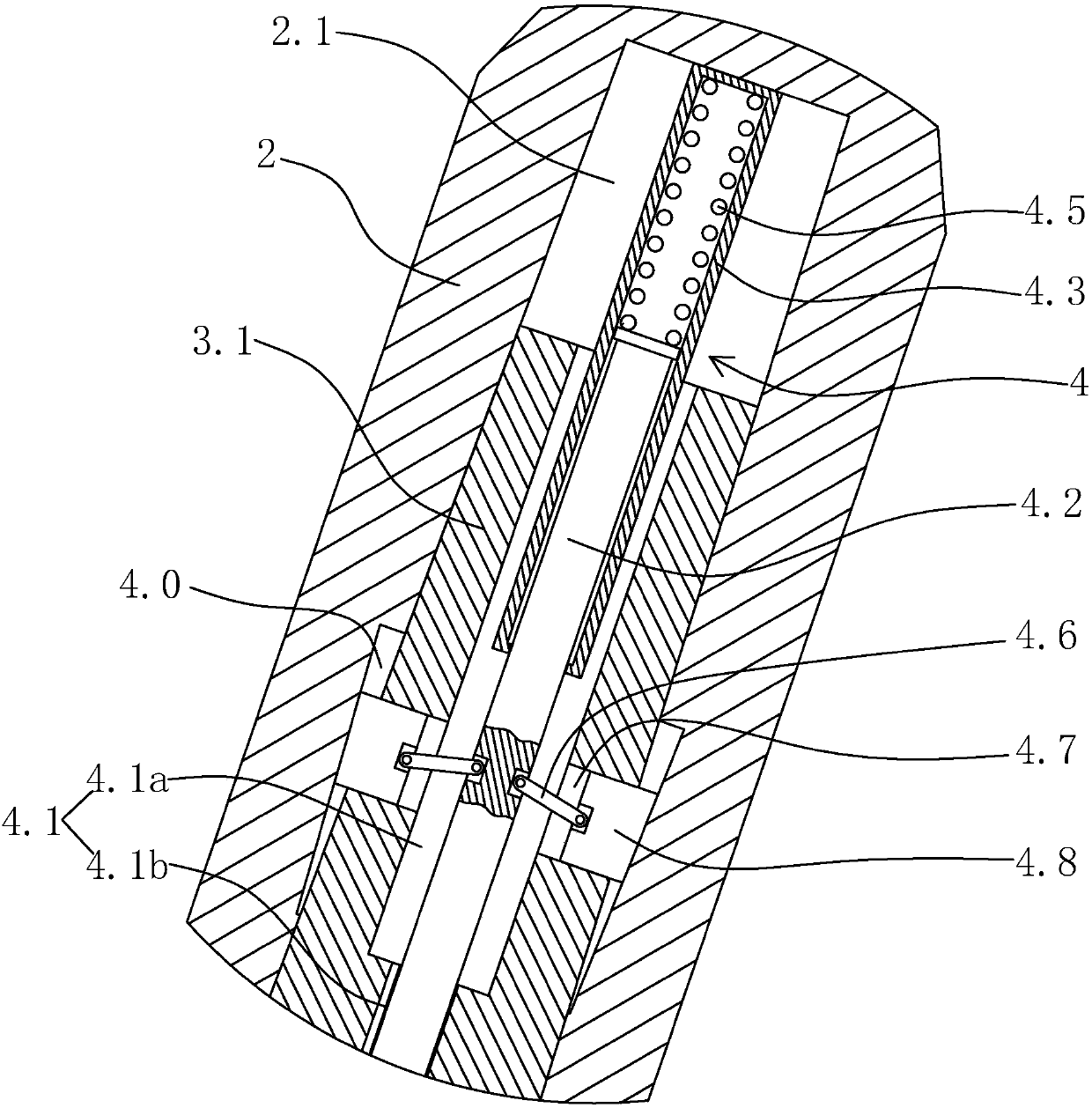
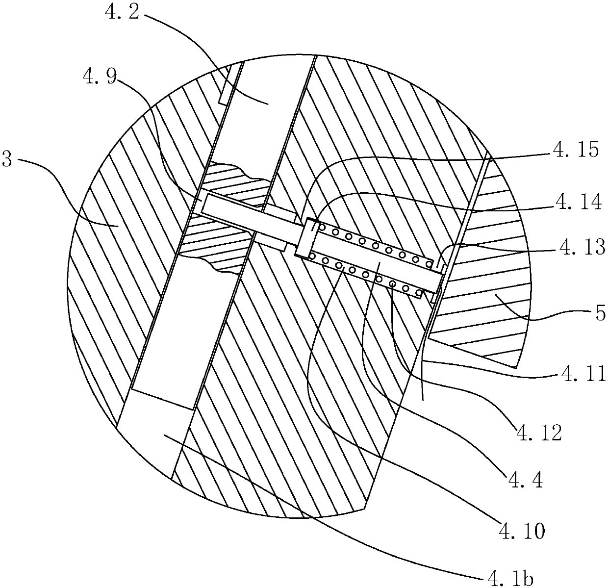
[0029] Such as figure 1 As shown in FIG. 1 , an easy-to-maintain tapered locking tension clamp includes a clamp body 1 and a drainage body. The clamp body is connected to the wire 6 . The upper part of the drainage body is connected with the clamp body, and the lower part of the drainage body is connected with the jumper 7 .

[0030] The clamp body includes an outer connection liner 1.1, a steel anchor and an inner connection liner 1.2. The steel anchor includes pull rings 1.3, liner connecting columns 1.5 and steel core connecting columns 1.6 distributed in sequence. A limit baffle 1.4 is arranged between the pull ring and the connecting column of the liner. The liner connecting column and the steel core connecting column are inserted into the outer connecting liner from the rear end of the outer connecting liner, and the limit baffle is ag...


PUM


Abstract

The invention discloses a conical locking type strain clamp convenient for maintenance, and aims to provide a conical locking type strain clamp which is not only convenient to assemble, disassemble and maintain, but also stable in strain clamp structure and capable of effectively solving a problem that the service life of the strain clamp is influenced and the power supply reliability is reduced due to looseness between an upper drainage member and a jumper drainage member. The conical locking type strain clamp comprises a clamp body and a drainage body, wherein the clamp body is connected with a wire. The drainage body comprises an upper drainage rod, a jumper drainage rod and a locking connecting nut, and is characterized in that the upper part of the upper drainage rod is connected withthe clamp body, and the lower end face of the upper drainage rod is provided with a conical insertion hole; the upper part of the jumper drainage rod is provided with a conical insertion rod matchedwith the conical insertion hole, and the conical insertion rod is inserted in the conical insertion hole; and the locking connecting nut is arranged on the jumper drainage rod in a sleeved manner. Thelower end of the upper drainage rod extends into the locking connecting nut, and the locking connecting nut is connected with the upper drainage rod through a thread.

Description

technical field [0001] The invention relates to a tension wire clamp, in particular to a tapered locking type tension wire clamp which is convenient for maintenance. Background technique [0002] The current strain clamp includes a clamp body and a drainage body. The clamp body is connected to the wire, and the drainage body usually includes an upper drain connected to the clamp body and a jumper drain connected to the jumper. The upper drain and the jumper drain are connected by nuts or bolts. The upper drainage part of the drainage body and the jumper drainage part are connected by bolts. Although this connection structure is convenient for maintenance and replacement, it is easy to connect the bolted upper drainage part and the jumper drainage part during the long-term use of the power line. Looseness occurs, and once there is looseness between the upper drainage piece and the jumper drainage piece, the resistance between the upper drainage piece and the jumper drainage ...

Claims


Application Information

Patent Timeline
IPC IPC(8): H02G7/05
Inventor 陈新安凌军郦晨钟王华秋闫小芳张凯高逢宇李志文汪哓哓黄崇达周来潜丽光陈艳来
Owner LISHUI POWER SUPPLY COMPANY OF STATE GRID ZHEJIANG ELECTRIC POWER
Features
  • Generate Ideas
  • Intellectual Property
  • Life Sciences
  • Materials
  • Tech Scout
  • Unparalleled Data Quality
  • Higher Quality Content
  • 60% Fewer Hallucinations
Learn More