Sound production device

A sound-generating device and a combined technology, applied in sensors, electrical components, loudspeakers, etc., can solve the problems of weakening the force of the magnetic circuit system on the voice coil and low-frequency THD distortion.

Active Publication Date: 2018-02-09
GOERTEK INC
View PDF8 Cites 0 Cited by
  • Summary
  • Abstract
  • Description
  • Claims
  • Application Information

AI Technical Summary

Problems solved by technology

At this time, the force of the magnetic circuit system on the voice coil is greatly weakened, coupled with the influence of the diaphragm stiffness coefficient at this time, it will cause large low-frequency THD distortion

Method used


Image

  • Sound production device
  • Sound production device
  • Sound production device

Examples


Embodiment Construction

[0027] Various exemplary embodiments of the present invention will now be described in detail with reference to the accompanying drawings. It should be noted that the relative arrangements of components and steps, numerical expressions and numerical values ​​set forth in these embodiments do not limit the scope of the present invention unless specifically stated otherwise.

[0028] The following description of at least one exemplary embodiment is merely illustrative in nature and in no way taken as any limitation of the invention, its application or uses.

[0029] Techniques, methods and devices known to those of ordinary skill in the relevant art may not be discussed in detail, but where appropriate, such techniques, methods and devices should be considered part of the description.

[0030] In all examples shown and discussed herein, any specific values ​​should be construed as exemplary only, and not as limitations. Therefore, other instances of the exemplary embodiment may...


PUM


Abstract

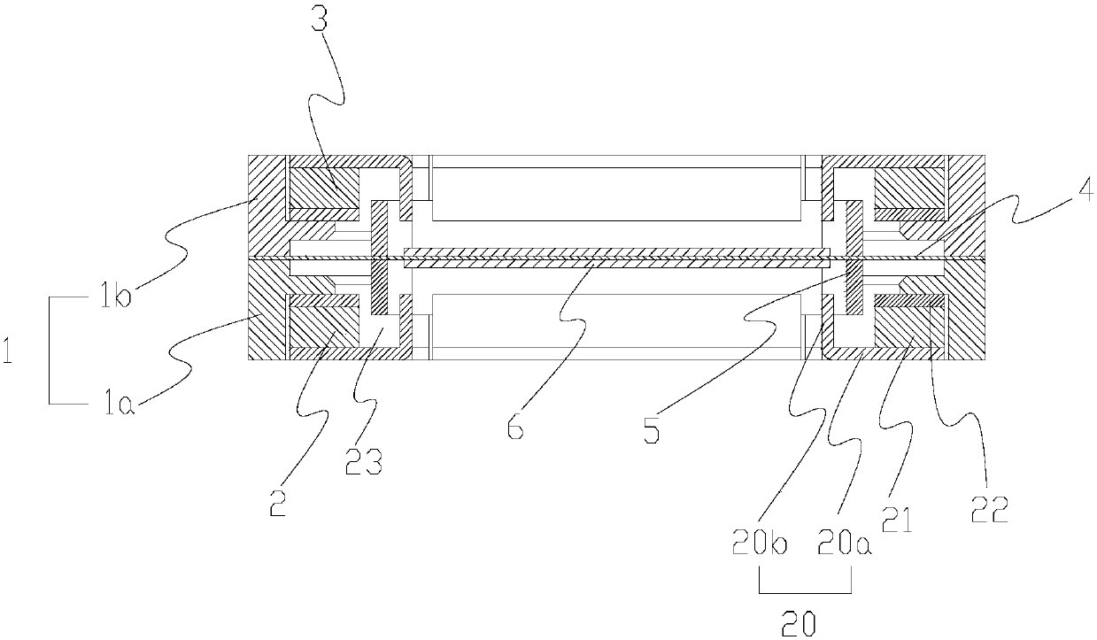
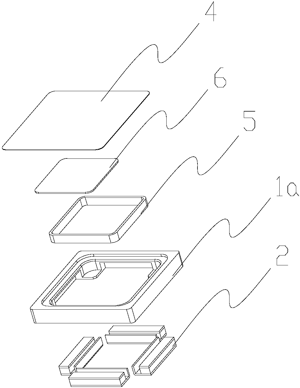
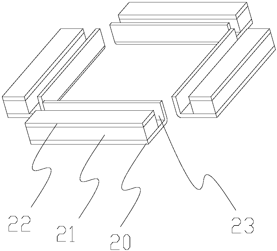
The invention discloses a sound production device which comprises a shell, a vibrating diaphragm and two magnetic circuit systems, wherein the vibrating diaphragm is arranged in the shell, and the magnetic circuit systems are symmetrically arranged on the two sides of the vibrating diaphragm, each magnetic circuit system comprises a magnetic yoke and a magnet arranged on the magnetic yoke, and themagnet is further provided with a washer. The sound production device further comprises two voice coils which are symmetrically distributed on the two sides of the vibrating diaphragm, one end of each voice coil is connected to the vibrating diaphragm, and the other end of each voice coil cooperates with the corresponding magnetic circuit system. According to the sound production device, the vibrating diaphragm matched with the magnetic circuit system can be more easily selected, so that the low-frequency distortion of the sound generation device and the distortion near the resonance frequency f0 can be greatly reduced through the cooperation of the vibrating diaphragm and the magnetic circuit systems.

Description

technical field [0001] The invention relates to the field of electroacoustic conversion, more specifically, to a sound generating device. Background technique [0002] The loudspeaker is an important acoustic device in electronic equipment, which includes a casing, a diaphragm installed in the casing, a voice coil fixedly connected to the diaphragm, and a magnetic circuit system. Among them, the voice coil is located in the magnetic gap formed by the magnetic circuit system. When the voice coil receives the audio signal, it drives the diaphragm to vibrate under the action of the magnetic circuit system, thereby instigating the surrounding air to make sound, and then realizing the conversion of electric energy to sound energy. convert. [0003] With this traditional loudspeaker structure, when it works at low frequencies, the voice coil will have a large displacement. At this time, the force of the magnetic circuit system on the voice coil is greatly weakened, coupled with ...

Claims


Application Information

Patent Timeline
IPC IPC(8): H04R9/06H04R9/02
CPCH04R9/02H04R9/06H04R2400/11
Inventor 霍亮刘岩涛
Owner GOERTEK INC
Why Eureka
Try Eureka