
Rotating controllable AIS (automatic identification system) base station binary Yagi antenna array

A Yagi antenna, controllable technology, applied in the direction of antennas, antenna parts, antenna supports/installation devices, etc., can solve the problem of communication channel occupation, difficult to quickly control the size of the lobe pattern, difficult to control the communication coverage of AIS base stations, etc. problem, to achieve the effect of increasing the impedance

Inactive Publication Date: 2018-02-13
SHANGHAI MARITIME UNIVERSITY
View PDF7 Cites 16 Cited by
  • Summary
  • Abstract
  • Description
  • Claims
  • Application Information

AI Technical Summary

Benefits of technology

This patented technology allows for an improved wireless communication system that uses multiple types of signals (Yagi) with different frequencies. It achieves this through use of both circularly polarized waves called Xylotropisescent Lines ("XLs") and linearly polarizing waveguides called Linear Optical Fibre." These techniques allow for better signal transmission over longer distances without losing much energy due to their high frequency content compared to traditional methods like radiofrequency identification tags.

Problems solved by technology

This patented technical problem addressed in this patents relating to improving the performance of marine radar systems involves monitoring their own positioning during cruising or shipping phases while also ensuring that they receive necessary data without overlapping with neighboring vessels or harbors. Current methods involve multiple types of devices like monopulse transponders, radioactive sources, and passive sonars. These conventional techniques require significant investment and maintenance costs due to the complexity involved in managing them.

Method used


Image

  • Rotating controllable AIS (automatic identification system) base station binary Yagi antenna array
  • Rotating controllable AIS (automatic identification system) base station binary Yagi antenna array
  • Rotating controllable AIS (automatic identification system) base station binary Yagi antenna array

Examples


Embodiment Construction

[0036] The present invention will be further elaborated below by describing a preferred specific embodiment in detail in conjunction with the accompanying drawings.

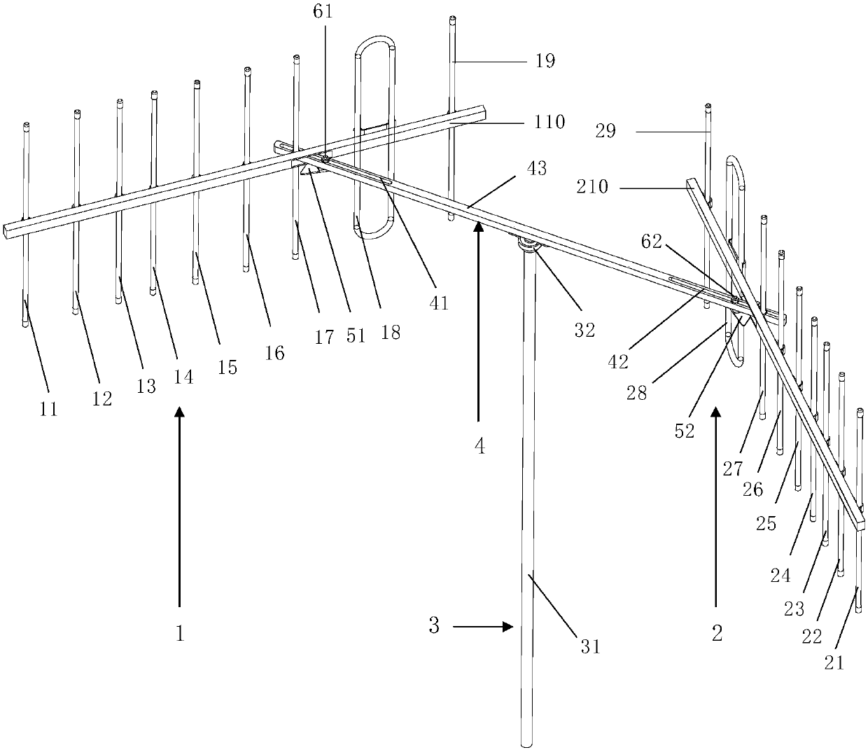
[0037] Such as figure 1 As shown, a rotating controllable AIS base station binary Yagi antenna array includes: a fixed shaft 3 arranged vertically; a main beam 4 with waist-shaped holes at both ends of the fixed shaft 3 arranged horizontally; a movable connector; a For the Yagi antenna, it is nested symmetrically on both sides of the main beam 4 and connected to the main beam 4 through a movable connector.

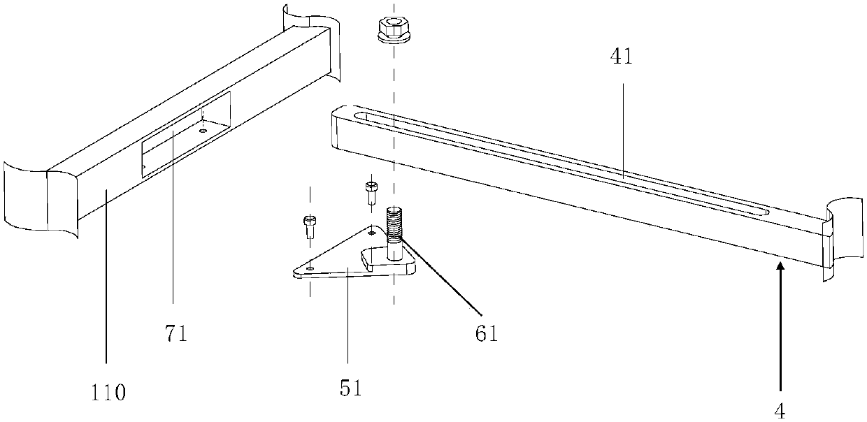
[0038] Each of the Yagi antennas includes: an antenna beam, and a rectangular through hole 71 is opened at the junction of the antenna beam and the main beam, so that the main beam passes through the rectangular through hole 71 to realize distance and rotation adjustment.

[0039] The two sides of the main beam 4 are respectively provided with a waist hole 41 and a waist hole 42;

[0040] Each of the Yagi a...


PUM


Abstract

The invention discloses a rotating controllable AIS (automatic identification system) base station binary Yagi antenna array, which comprises a vertically arranged fixed shaft, a main beam, an movableconnecting element and a pair of Yagi antennas, wherein the main beam is horizontally arranged at the two ends of the fixed shaft and is provided with a kidney-shape hole; the pair of Yagi antennas are symmetrically arranged at the two sides of the main beam in a sleeving way and are connected with the main beam through a movable connecting element; each Yagi antenna comprises an antenna cross beam; a rectangular through hole is formed in a connecting position of the antenna cross beam and the main beam, so that the main beam passes through the rectangular through hole to realize the distanceand rotating regulation. The ship routing scheme water area AIS base station communication requirements can be met, so that the safety of the ship routing scheme water area can be improved.

Description


Claims


Application Information

Patent Timeline
Owner SHANGHAI MARITIME UNIVERSITY
Learn More