Erecting method for chamfered setting steel formwork

A technology for shaping steel and steel formwork, which is used in water conservancy projects, artificial islands, underwater structures, etc. It can solve the problems of excessively large formwork joints at the chamfered corners and insufficient rigidity of the formwork at the chamfered corners. Skilled and good looking effect

Active Publication Date: 2018-02-16
CHINA MCC17 GRP
View PDF3 Cites 4 Cited by
  • Summary
  • Abstract
  • Description
  • Claims
  • Application Information

AI Technical Summary

Problems solved by technology

[0004] Aiming at the defects and deficiencies in the prior art, the present invention provides a support method for chamfered and shaped steel formwork, which can solve the problem of too large formwork joints at the chamfered corners, insufficient rigidity of the formwork at the chamfered corners, and the difference between the shaped steel formwork and the wooden formwork. (Plastic formwork) How to splice and reinforce mixed use

Method used


Image

  • Erecting method for chamfered setting steel formwork
  • Erecting method for chamfered setting steel formwork
  • Erecting method for chamfered setting steel formwork

Examples


Embodiment 1

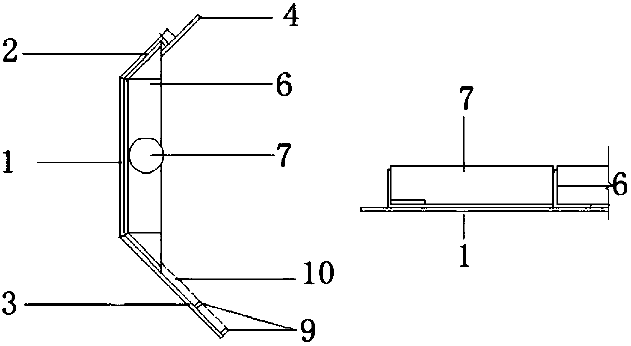
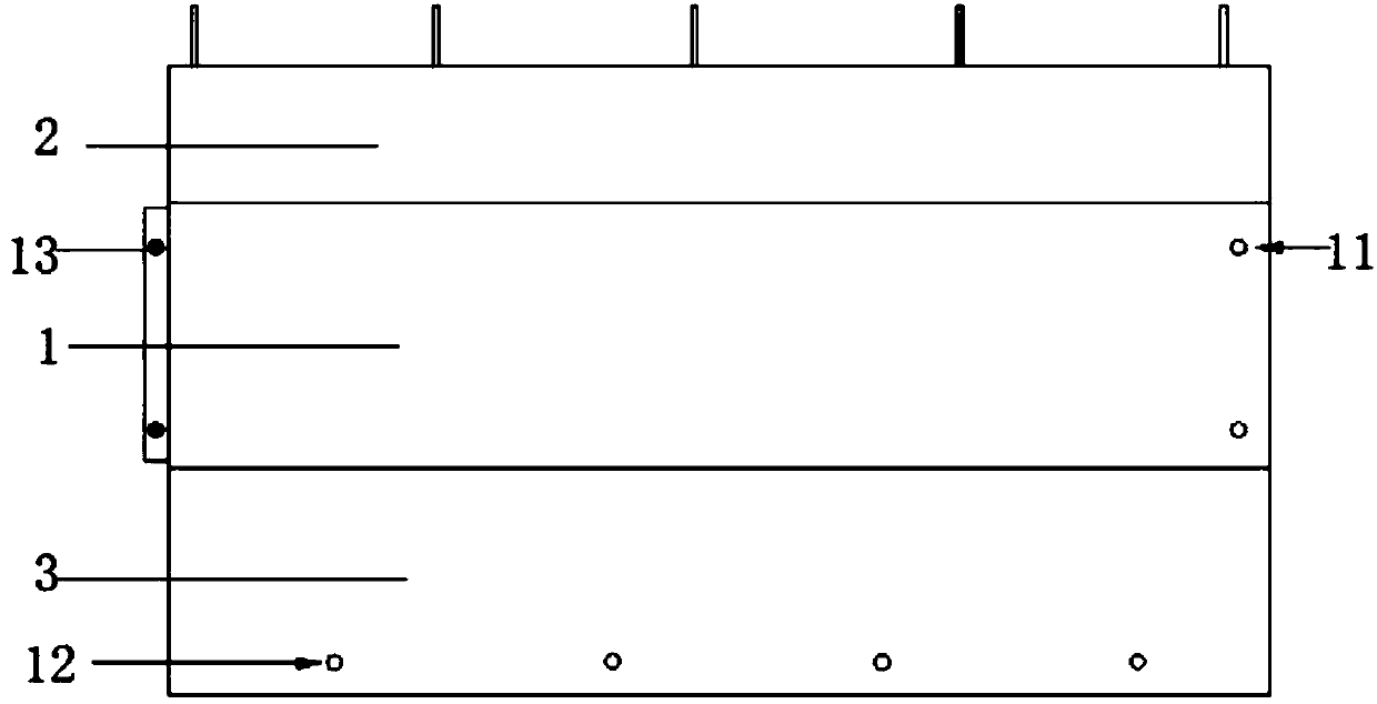
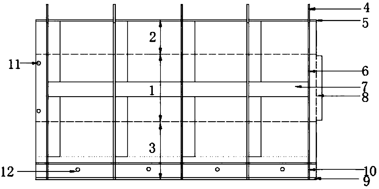
[0039] exist figure 1 Among them, a method for supporting a chamfered and shaped steel formwork in this embodiment, the chamfered and shaped steel formwork includes a web steel plate 1, an upper flange steel plate 2 and a lower flange steel plate 3, and the web steel plate 1 and the upper flange steel plate A main stiffener 5 is arranged between the flange steel plates 2; a main stiffener 5 is arranged between the web steel plate 1 and the lower flange steel plate 3; 50 steel pipes 7 are welded between the main stiffeners 5; The end of the upper flange steel plate 2 is welded with an upper flange end stand plate 6 and a drag claw 4; the lower flange steel plate 3 is welded with a longitudinal secondary stiffener 9 and a transverse secondary stiffener 10; the described One end of the lower flange steel plate 3 is provided with a plurality of bolt holes 12; one end of the web steel plate 1 is provided with a butt plate 8; the butt plate 8 is provided with a pin 13; The other en...


PUM


Abstract

The invention discloses an erecting method for a chamfered setting steel formwork and belongs to the technical field of construction methods for constructional engineering. The erecting method for thechamfered setting steel formwork comprises the steps that 1, the chamfered setting steel formwork is manufactured at first according to the chamfering size; 2, a web formwork and an upper flange formwork are welded through equal leg angle main stiffening ribs, and the web formwork and a lower flange formwork are welded through equal leg angle main stiffening ribs, so that the integrality is enhanced; 3, steel pipes are welded between the main stiffening ribs; 4, an upper flange end stopping board is welded to the end portion of an upper flange and used for controlling the sectional dimension;5, longitudinal secondary stiffening ribs and transverse secondary stiffening ribs are welded to a lower flange; 6, bolt holes are drilled in the middles of the longitudinal secondary stiffening ribs; 7, a wall formwork is erected; 8, a platform formwork is erected; and 9, the lower flange is in butt joint with an erected wall. By means of the erecting method for the chamfered setting steel formwork, the problems that splicing beams at the chamfered position of the formwork are too large and the rigidity of the chamfered position of the formwork is poor can be solved, and splicing and reinforcing of combined use of the setting steel formwork with a wood formwork (or a plastic formwork) can also be achieved.

Description

technical field [0001] The invention relates to the technical field of construction methods on construction sites, and more specifically, relates to a method for supporting a chamfered and shaped steel formwork. Background technique [0002] In recent years, with the development of civil engineering construction technology, more and more special-shaped formworks have emerged, and chamfering formwork is one of them. Chamfer formwork is widely used, especially in the field of large-scale infrastructure construction, such as pipe gallery projects. The pipe gallery project has a long mileage and the inside of the outer wall needs to be poured into a 45° chamfer, and the amount of chamfer formwork is large. The use of traditional wooden formwork and plastic formwork at the chamfers has large formwork joints, low rigidity and easy deformation, and the quality of concrete molding is difficult to guarantee; the cost of using integrally shaped steel formwork and aluminum alloy formw...

Claims


Application Information

Patent Timeline
Patent Type & Authority Applications(China)
IPC IPC(8): E02D29/045
Inventor 李志路胡定君
Owner CHINA MCC17 GRP
Why Eureka
Try Eureka