Tracer particle sowing device for two-phase flow field PIV measurement and operation method

A technology of tracer particles and operation methods, which is applied in the directions of measuring devices, fluid velocity measurement, velocity/acceleration/impact measurement, etc., can solve problems such as measurement result deviation and wrong measurement results, and achieve easy processing, improve spreading efficiency, and solve Effects of Blending and Interference

Active Publication Date: 2018-02-16
HARBIN ENG UNIV
View PDF10 Cites 6 Cited by
  • Summary
  • Abstract
  • Description
  • Claims
  • Application Information

AI Technical Summary

Problems solved by technology

When the tracer particles are spread into the measured flow field, the uniformity of the tracer particles in the flow field will have a greater impact on the measurement results. If the distribution is uneven, it will not be able to reflect the true information of the measured flow field. Make the measurement results have a large deviation, and even produce wrong measurement results

Method used


Image

  • Tracer particle sowing device for two-phase flow field PIV measurement and operation method
  • Tracer particle sowing device for two-phase flow field PIV measurement and operation method
  • Tracer particle sowing device for two-phase flow field PIV measurement and operation method

Examples


Embodiment 1

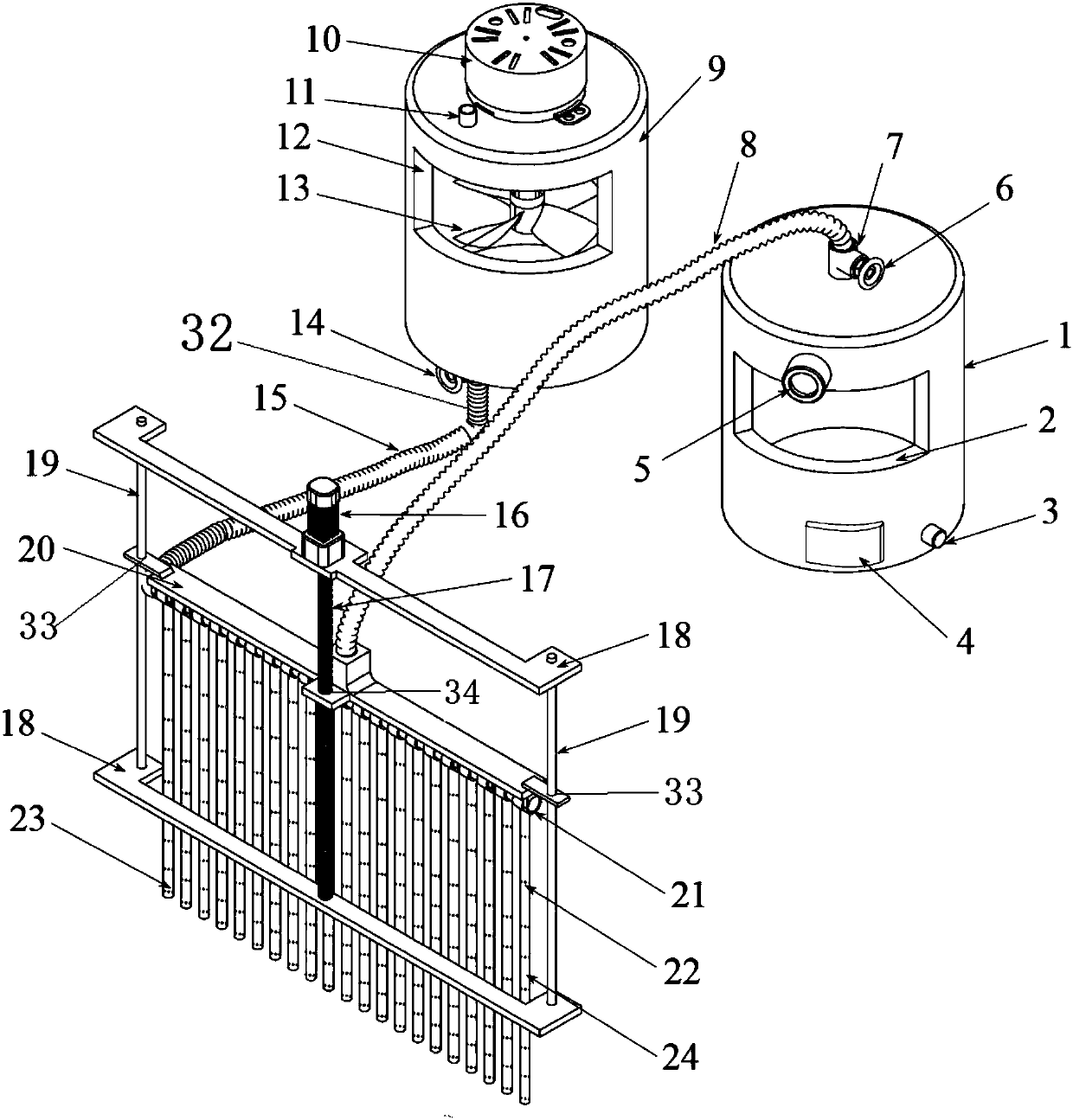
[0044] When used for the PIV measurement of two-phase flow field, a certain amount of tracer particles are injected into the cylindrical pressure-holding tank 1 and the tank 9 with a mixer through the funnel-shaped guide pipe from the air inlet 3 and the water inlet 11 respectively. At this time, both the first valve 6 and the second valve 14 are in the closed state. Remove the funnel-shaped guide pipe then, and air and water are sent into the tank body from the air inlet 3 and the water inlet 11 respectively by the air compressor and the water pump. When the pressure value shown by the pressure gauge 5 on the cylindrical pressure-holding tank 1 reaches the predetermined pressure, remove the air compressor and close the air inlet 3; when the water level in the tank 9 with the mixer reaches the predetermined water level, remove the The water pump closes the water inlet, and opens the stirring device 13 for stirring. After a certain period of time, the first motor 10 is turned ...

Embodiment 2

[0046] When used in a single-phase flow field, only one corresponding tank body is used in Embodiment 1, and the other tank is closed.

[0047] The given examples are given only to aid in the illustration of the invention and are not intended to be limiting.

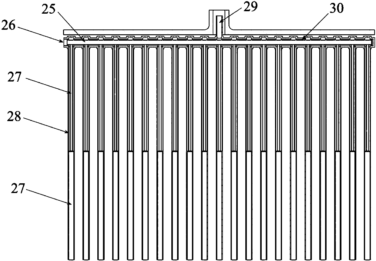
[0048] Compared with the prior art, the tank premixing device adopted in the present invention can premix the tracer particles in the gas phase and the liquid phase synchronously, which greatly saves time and cost. The cylindrical pressure-holding tank body can realize the pressure-holding delivery of particles, and the structure is simple, safe and reliable. The liftable particle releaser realizes the free lifting of the particle releaser through the simple structure of the motor and the screw rod, ensuring that the particles can be delivered to the measurement area quickly and accurately. The special pipeline structure adopted by the particle releaser effectively solves the problem of mutual mixing and interference of...


PUM


Abstract

The invention belongs to the field of fluid velocity field measurement, and relates to a tracer particle sowing device for two-phase flow field PIV measurement and an operation method. The problem that tracer particles cannot be effectively sowed in a two-phase flow field PIV measurement experiment at the same time in the prior art is solved. The device comprises a cylindrical pressure holding tank body, a tank body with a mixer, and a lifting particle release. The cylindrical pressure holding tank body comprises a first observation window, an air inlet, a safety valve, a pressure gauge, a first valve, an air outlet and a first hose. The tank body with the mixer comprises a first motor, a water inlet, a second observation window, the mixer, a second valve, a second hose and a water outlet.The lifting particle release comprises a second motor, a screw, a support frame, a connecting rod, a top steel plate, a horizontal pipe and a vertical circular pipe. The device provided by the invention has the advantages of wide application, simple operation and high reliability.

Description

technical field [0001] The invention belongs to the field of fluid velocity field measurement, and in particular relates to a tracer particle spreading device and an operation method for two-phase flow field PIV measurement. Background technique [0002] At present, the methods for measuring liquid flow field are: (1) ratio managed velocimetry; (2) hot wire / hot film velocimetry; (3) LDV laser Doppler and related technologies; (4) PIV technology. [0003] The laser Doppler velocimeter measures the Doppler signal of the tracer particles passing through the laser probe, and then obtains the speed according to the relationship between the speed and the Doppler frequency. Because it is a laser measurement, there is no interference to the flow field, and the speed measurement range is wide, and because the Doppler frequency and speed are linearly related, it has nothing to do with the temperature and pressure at this point. It is currently the most accurate speed measurement instr...

Claims


Application Information

Patent Timeline
Patent Type & Authority Applications(China)
IPC IPC(8): G01P5/20
CPCG01P5/20
Inventor 王恋舟郭春雨赵大刚薛嵘徐佩宋妙妍张东汗
Owner HARBIN ENG UNIV
Why Eureka
Try Eureka