Shifting fork type butterfly valve

A fork type, butterfly valve technology, applied in the direction of lift valve, valve details, valve device, etc., can solve the problems of poor sealing of connecting pipes and reduced work efficiency.

Active Publication Date: 2018-02-23
ANHUI RONGDA VALVE
View PDF6 Cites 2 Cited by
  • Summary
  • Abstract
  • Description
  • Claims
  • Application Information

AI Technical Summary

Problems solved by technology

[0003] The purpose of the present invention is to solve the problem in the prior art that the connecting pipe at the water outl

Method used


Image

  • Shifting fork type butterfly valve
  • Shifting fork type butterfly valve
  • Shifting fork type butterfly valve

Examples


Embodiment Construction

[0019] The following will clearly and completely describe the technical solutions in the embodiments of the present invention with reference to the accompanying drawings in the embodiments of the present invention. Obviously, the described embodiments are only some, not all, embodiments of the present invention.

[0020] In describing the present invention, it should be understood that the terms "upper", "lower", "front", "rear", "left", "right", "top", "bottom", "inner", " The orientation or positional relationship indicated by "outside", etc. is based on the orientation or positional relationship shown in the drawings, and is only for the convenience of describing the present invention and simplifying the description, rather than indicating or implying that the referred device or element must have a specific orientation, so as to Specific orientation configurations and operations, therefore, are not to be construed as limitations on the invention.

[0021] refer to Figure ...


PUM


Abstract

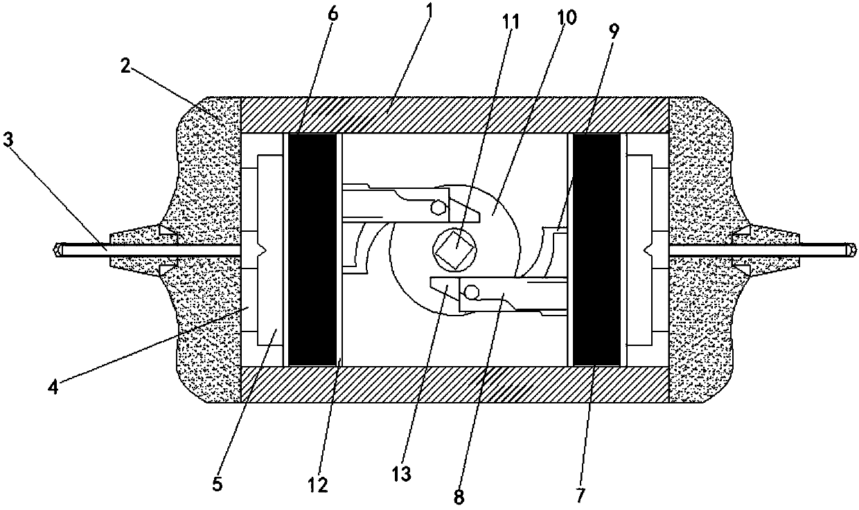
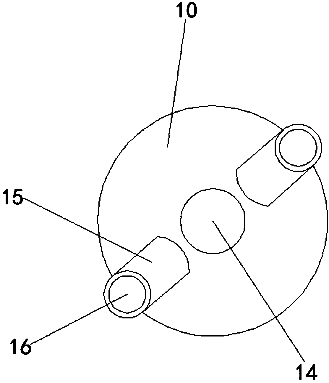
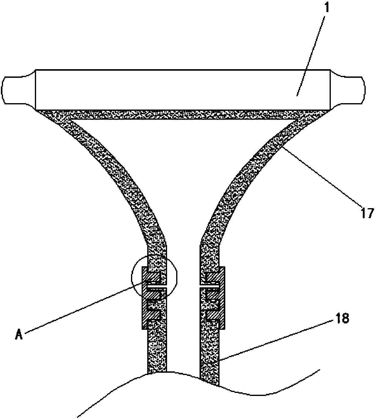
The invention discloses a shifting fork type butterfly valve. The shifting fork type butterfly valve comprises two parallelly arranged fixing plates. Fixed blocks are fixedly connected to the two sides of each of the two fixing plates correspondingly, the sides, away from the fixing plates, of the fixed blocks are of arc-shaped structures protruding outwards, embedded blocks are arranged at the two ends of each fixed block in a clamped mode correspondingly, connecting rods are inserted into the embedded blocks, and the connecting rods penetrate through the embedded blocks to be connected withthe fixed blocks; shifting fork devices are arranged between the fixing plates and the fixed blocks, two parallelly arranged sealing blocks are arranged on each shifting fork device, and the two endsof each sealing block abut against the fixing plates; and installation blocks are fixedly connected to the side walls of one opposite sides of the sealing blocks correspondingly, and two parallelly arranged connecting blocks are fixed to the side, away from the corresponding sealing block, of each installation block. According to the shifting fork type butterfly valve, the structure is simple, operation is convenient, the airtightness between the butterfly valve and a connecting pipe is improved based on an existing shifting fork type butterfly valve structure, the water leakage possibility isreduced, and the working efficiency of the butterfly valve is improved.

Description

technical field [0001] The invention relates to the technical field of butterfly valves, in particular to a fork type butterfly valve. Background technique [0002] Butterfly valve, also known as flap valve, is a regulating valve with simple structure, which can be used for switching control of low-pressure pipeline medium. A kind of valve, the valve can be used to control the flow of various types of fluids such as air, water, steam, various corrosive media, mud, oil, liquid metal and radioactive media. It mainly plays the role of cutting and throttling on the pipeline. The opening and closing part of the butterfly valve is a disc-shaped butterfly plate, which rotates around its own axis in the valve body, so as to achieve the purpose of opening and closing or adjustment. Most of the current butterfly valves are opened and closed by a fork structure or a gear structure. And its outlet is often connected by connecting pipe, but the connection between connecting pipe and bu...

Claims


Application Information

Patent Timeline
IPC IPC(8): F16K1/226F16K1/22F16K27/02F16L21/00
CPCF16K1/221F16K1/226F16K27/0218F16L21/00
Inventor 胡启明
Owner ANHUI RONGDA VALVE
Why Eureka
Try Eureka