Temperature control valve group of fan coil

A technology for fan coil units and temperature control valves, applied in valve details, multi-way valves, valve devices, etc., can solve problems such as changing pipelines, excessive pressure in pipelines, blocked backflow, etc., and achieve fast and convenient construction and good market promotion value Effect

Active Publication Date: 2018-02-23
TAIZHOU BANCHENG HVAC TECH CO LTD
View PDF1 Cites 0 Cited by
  • Summary
  • Abstract
  • Description
  • Claims
  • Application Information

AI Technical Summary

Problems solved by technology

[0004] Aiming at the prior art, the present invention provides a novel modularized fan coil temperature control valve group, which can solve the problems of excessive pressure changes in pipelines and pipeline blockage and backflow. At the same time, the product structure is simple and can be applied to fan coils with different distances interface, the overall structure is safer and more reliable, and the construction is convenient and flexible

Method used


Image

  • Temperature control valve group of fan coil
  • Temperature control valve group of fan coil
  • Temperature control valve group of fan coil

Examples


Embodiment Construction

[0018] The present invention will be further described below in conjunction with preferred embodiments.

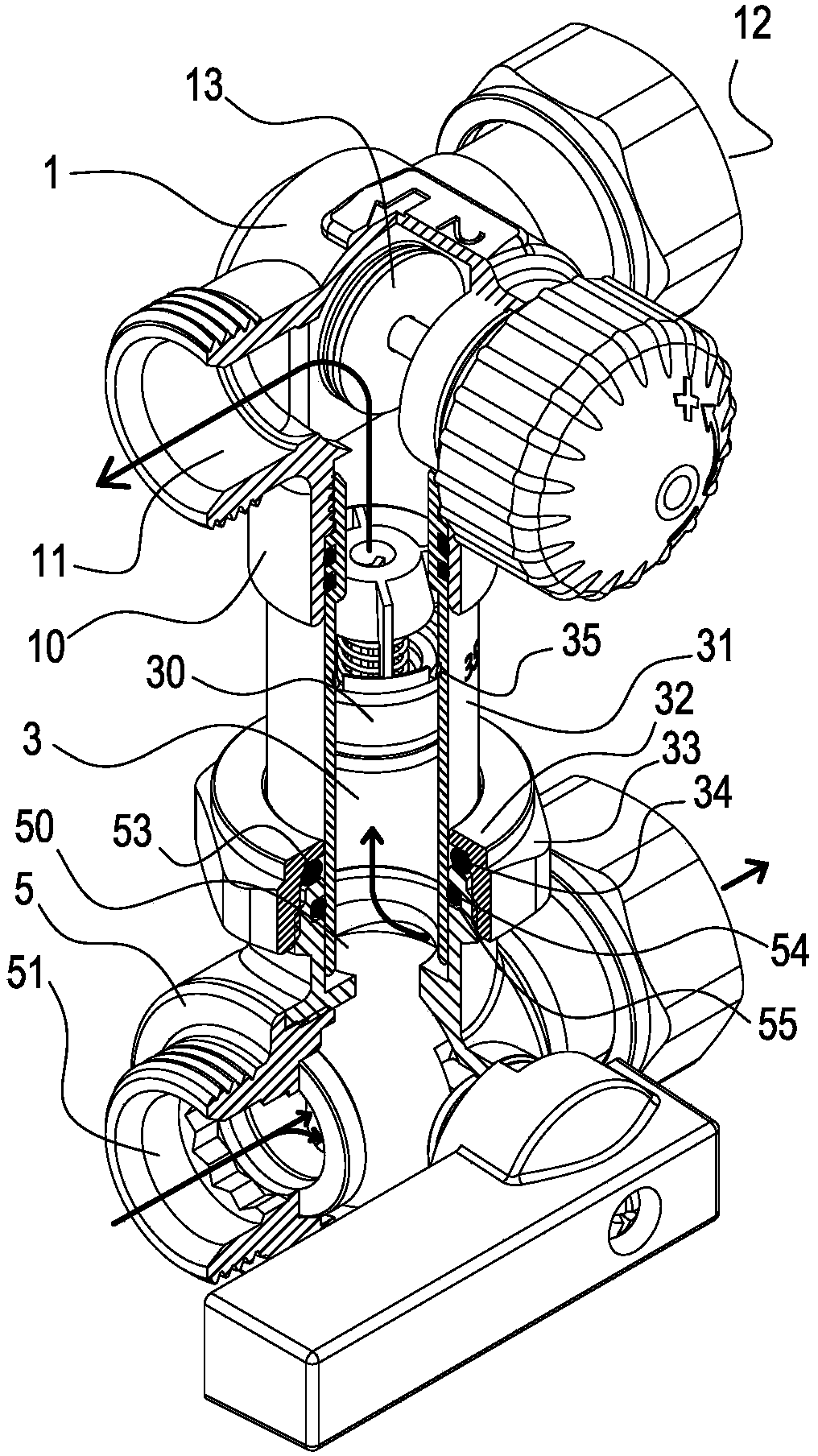
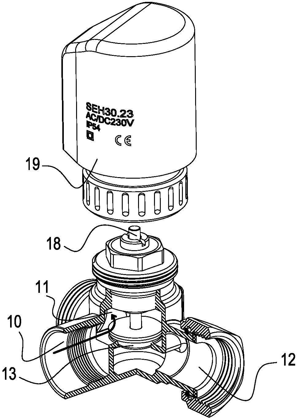
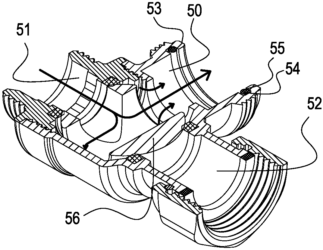
[0019] like Figure 1 to Figure 3 As shown, a fan coil temperature control valve group includes a three-way side-inlet regional valve 1, and the lower port 10 of the three-way side-inlet regional valve 1 communicates with a middle cavity 3, and the middle cavity 3 is equipped with The pressure difference spool part 30 of the top stop is connected to the upper port 50 of the three-way side goal valve 5; the lower water inlet 51 at the left end of the three-way side goal valve 5 is always connected with the middle cavity 3; the three-way The upper water outlet 11 at the left end of the side entry area valve 1 is always in communication with the middle cavity 3, and is opened and closed through the area valve core 13 and the upper water inlet 12; the outer wall of the middle cavity 3 is an extension pipe part 31, the extension pipe The part 31 is separated from the ball valv...


PUM


Abstract

The invention relates to a front end temperature control valve group of a fan coil of a central air conditioner. The temperature control valve group of the fan coil comprises a tee side-entering areavalve, and a middle cavity communicates with an end opening of the lower side of the tee side-entering area valve; the middle cavity is internally provided with a bottom-passing top-stopping pressuredifferential valve core part, and the middle cavity communicates with the end opening of the upper side of a tee side-entering ball valve; a lower water inlet of the left end of the tee side-enteringball valve communicates with the middle cavity all the time; and an upper water outlet of the left end of the tee side-entering area valve communicates with the middle cavity all the time, and openingand closing of the upper water outlet and the upper water inlet are realized through an area valve core. According to the front end temperature control valve group of the fan coil of the central airconditioner, a pressure difference circulating reflux pipeline is achieved at the front end of the fan coil, and pressure balance of the pipeline is protected; in addition, an extending pipe part andthe tee side-entering ball valve adopt the split structure, and the telescopic distance adjusting function of the front end temperature control valve group meets the connecting problem of different fan coil joint spacings; and the connecting mode is changed, so that the whole assembly makes construction quick, convenient, safe and reliable, and the front end temperature control valve group has very good market promotion value.

Description

technical field [0001] The invention relates to the technical field of air conditioning, in particular to a temperature control valve group at the front end of a fan coil unit of a central air conditioner. Background technique [0002] The fan coil unit is located at the end of the central air conditioner, and transports air with regulated temperature into the corresponding indoor space. In order to maintain the indoor air temperature, the cold and heat sources entering the fan coil unit can be switched or flow controlled. The commonly used solution is to connect a zone valve at the front end of the fan coil unit, and control the valve actuator acting on the zone valve through the indoor temperature control panel to realize the opening and cutting of the cold and heat sources of the pipeline to achieve temperature control. A regional valve similar to the prior art is shown in "A Two-way Regional Valve" with the announcement number CN 202149229 U. [0003] In construction p...

Claims


Application Information

Patent Timeline
Patent Type & Authority Applications(China)
IPC IPC(8): F16K11/10F16K27/00
CPCF16K11/10F16K27/00
Inventor 黄晓峰
Owner TAIZHOU BANCHENG HVAC TECH CO LTD
Why Eureka
Try Eureka