Resin tank fixing structure

A technology of fixed structure and resin tank, applied in the direction of ion exchange water/sewage treatment, etc., can solve the problem of easy shaking and slipping of the resin tank, and achieve the effect of small occupied space, avoiding tilting and shaking, and easy installation.

Inactive Publication Date: 2018-03-06
NANJING FOBRITE ENVIRONMENTAL TECH
View PDF0 Cites 0 Cited by
  • Summary
  • Abstract
  • Description
  • Claims
  • Application Information

AI Technical Summary

Problems solved by technology

In this way, the resin tank is prone to shaki

Method used


Image

  • Resin tank fixing structure
  • Resin tank fixing structure
  • Resin tank fixing structure

Examples


Example Embodiment

[0013] The present invention will be further explained below in conjunction with the drawings.

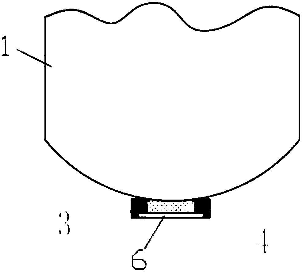
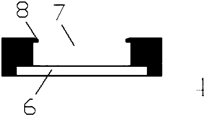
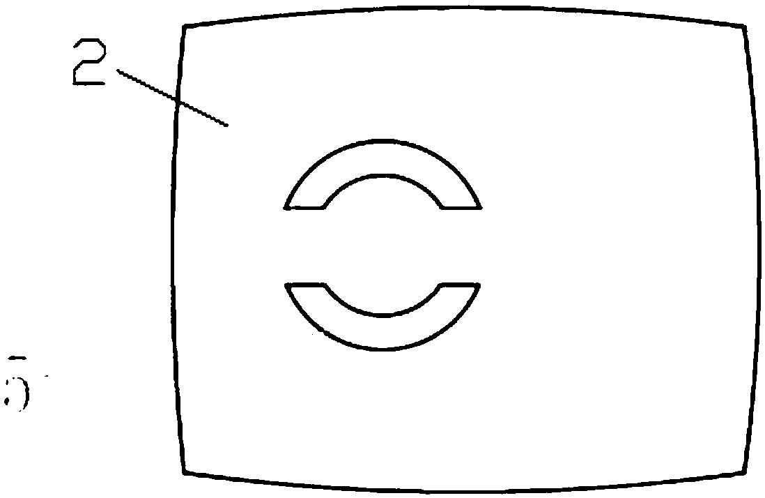
[0014] Such as Figure 1 to 3 As shown, a resin tank fixing structure of the present invention includes a resin tank 1 and a bottom bracket 4. The bottom of the resin tank 1 is provided with a rectangular boss 3, and the rectangular boss 3 and the upper part of the bottom bracket 4 are connected by a card slot. The card slot is arranged on the side of the rectangular boss 3, and the card slot is a horizontally arranged strip slot. The upper part of the bottom bracket 4 is provided with a square groove 7 that matches the rectangular boss 3, and the notch of the square groove 7 is provided with a hook 8 that matches the groove. A circular groove 6 is provided in the lower part of the bottom bracket 4. In order to stabilize the resin tank 1, the bottom plate 2 of the casing of the existing water softener is provided with an annular boss 5, and the circular groove 6 is exactly matched ...


PUM


Abstract

The invention discloses a resin tank fixing structure. The resin tank fixing structure comprises a resin tank, wherein a rectangular lug boss is arranged at the bottom of the resin tank; the rectangular lug boss is connected with the upper part of a bottom bracket through a clamping slot; a circular groove is formed in the lower part of the bottom bracket; the clamping slot is formed in the side surface of the rectangular lug boss; a square groove matched with rectangular lug boss is formed in the upper part of the bottom bracket; and a clamping hook matched with the clamping slot is arrangedat a groove opening position of the square groove. The resin tank fixing structure can steadily fix the resin tank in a water softening machine body, so that a tilting and shaking phenomenon of the resin tank is avoided and a safety problem caused by leakage of the resin tank is prevented; and in addition, the resin tank fixing structure occupies small space and is convenient to mount.

Description

Technical field [0001] The invention relates to the field of water softening equipment, in particular to a resin tank fixing structure for a water softening integrated machine. Background technique [0002] With the development of the water softener industry, water softeners have slowly entered the ranks of households. In order to save space, household water softeners are generally designed to be as small as possible. However, the size of the all-in-one machine is often affected by the components of the water softener, and the resin tank occupies the largest space. [0003] The resin tank is processed and formed by rotational molding. Generally, the bottom surface of the resin tank is a hemispherical surface, which is not conducive to vertical placement. Therefore, each resin tank is equipped with a corresponding base to facilitate flat placement. But in this way, the space for installing into the all-in-one machine will be seriously insufficient, so currently, the built-in base i...

Claims


Application Information

Patent Timeline
IPC IPC(8): C02F1/42
CPCC02F1/42
Inventor 薛永倪雷
Owner NANJING FOBRITE ENVIRONMENTAL TECH
Why Eureka
Try Eureka