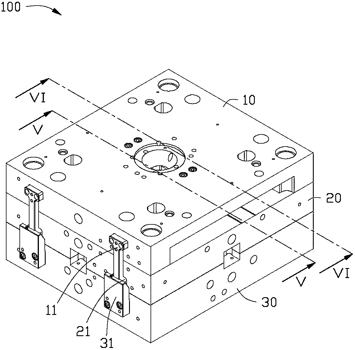
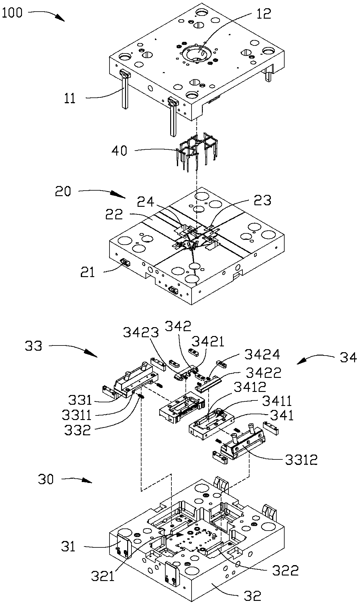
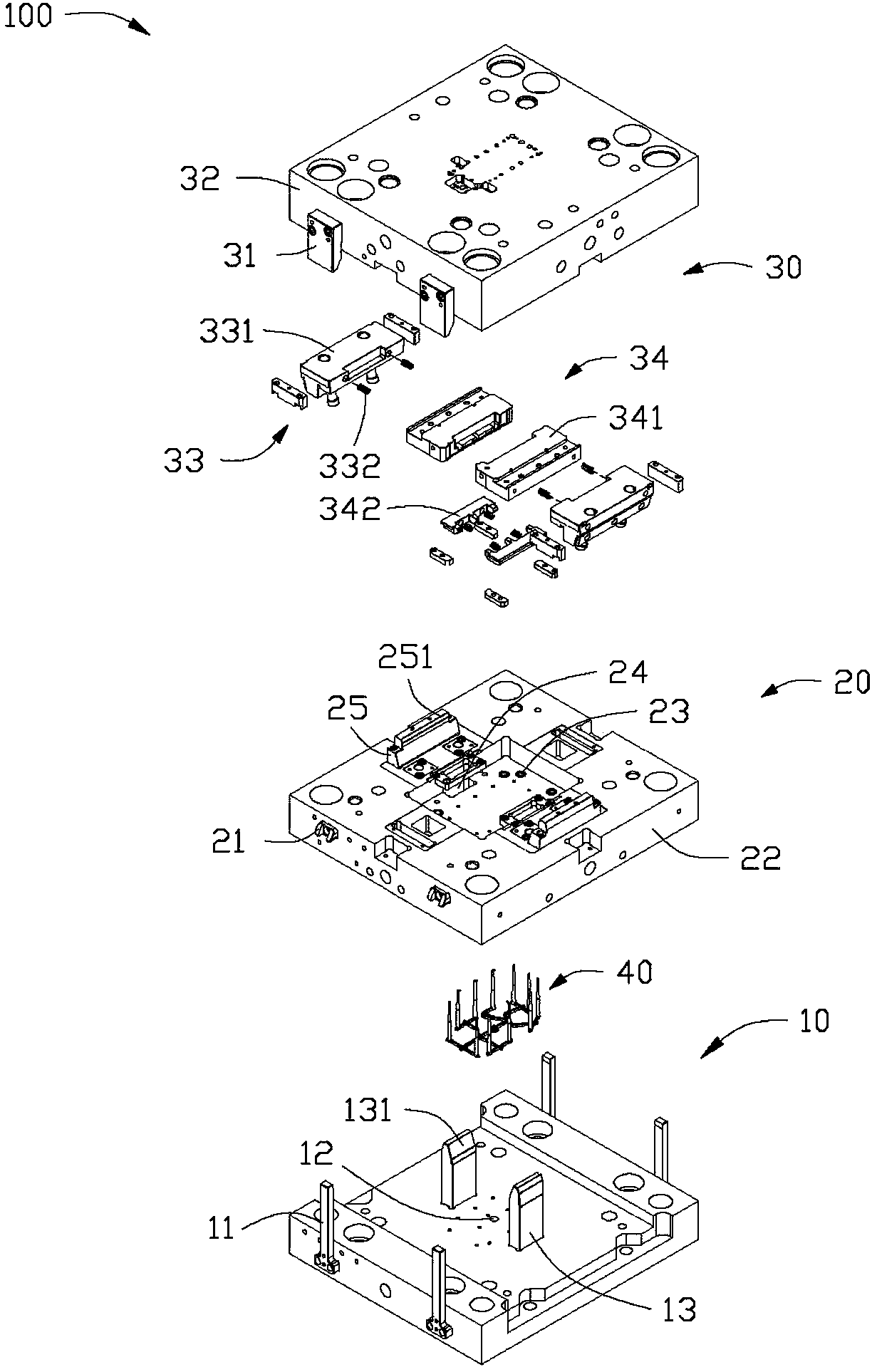
Injection molding mold

An injection mold and injection cavity technology, which is applied in the field of injection molds where the pouring head is not easy to break, can solve the problems such as the risk of mold compression, the increase of mold injection pressure, and the breaking and falling off of the runner.

Active Publication Date: 2018-03-13
富联科技(武汉)有限公司
View PDF7 Cites 8 Cited by
  • Summary
  • Abstract
  • Description
  • Claims
  • Application Information

AI Technical Summary

Problems solved by technology

However, the setting of the runner can easily lead to an increase in the injection pressure of the mold, causing the plastic to overflow and form waste, and the runner is easy to break off from the pouring head, causing the mold to have a risk of compression molding, thereby affecting the molding of the workpiece and resulting in the effect of the molding of the workpiece poor

Method used


Image

  • Injection molding mold
  • Injection molding mold
  • Injection molding mold

Examples


Embodiment Construction

[0015] The technical solutions in the embodiments of the present invention will be clearly and completely described below in conjunction with the accompanying drawings in the embodiments of the present invention. Obviously, the described embodiments are only part of the embodiments of the present invention, not all of them. Based on the implementation manners in the present invention, all other implementation manners obtained by persons of ordinary skill in the art without making creative efforts belong to the scope of protection of the present invention.

[0016] It should be noted that when a component is considered to be "connected" to another component, it may be directly connected to the other component or there may be an intervening component at the same time.

[0017] Unless otherwise defined, all technical and scientific terms used herein have the same meaning as commonly understood by one of ordinary skill in the technical field of the invention. The terminology used ...


PUM


Abstract

The invention relates to an injection molding mold, which comprises a top mold, a middle mold, a bottom mold and a pouring head accommodated in the middle mold in a penetrating manner, wherein the topmold comprises an incident hole and first bear-against blocks, the middle mold comprises a first body, a pouring head penetrating hole, a bear-against block penetrating hole and a second bear-againstblock, the pouring head penetrating hold is used for accommodating the pouring head, the bear-against block penetrating hole is used for the penetrating of the first bear-against block, the second bear-against block is arranged at the middle mold surface facing the bottom mold, the bottom mold comprises a second body, an injection molding cavity arranged inside the second body, first sliding members slidably arranged inside the second body, and a second sliding member connected to the first sliding members, the second bear-against block bears against the first sliding member so as to slide, the second sliding member comprises a fixation block and a second sliding block arranged inside the fixation block, the fixation block is provided with an injection hole, the second sliding block comprises a bear-against part arranged corresponding to the injection hole, the pouring head comprises a material guide strip, a conduction pipe connected to the material guide strip, and a glue port connected to the conduction pipe, the glue port is accommodated into the injection hole, and the bear-against part slidingly bears against the glue port.

Description

technical field [0001] The invention relates to an injection mold, in particular to an injection mold whose pouring head is not easy to break. Background technique [0002] In the field of injection molding, in order to realize the injection molding of the workpiece, the existing process is usually to place the pouring head in the mold, then close the mold, and inject plastic, etc. into the cavity of the mold through the pouring head. Generally, a section of runner is separately provided on the traditional pouring head, through which plastics are injected. However, the setting of the runners will easily lead to an increase in the injection pressure of the mold, causing the plastic to overflow and form waste, and the runners will easily break off from the pouring head, which will cause the mold to have a risk of compression molding, thereby affecting the molding of the workpiece and resulting in the effect of the molding of the workpiece poor. Contents of the invention ...

Claims


Application Information

Patent Timeline
Patent Type & Authority Applications(China)
IPC IPC(8): B29C45/26B29C45/27B29C45/33
Inventor 黄婵娟芮发明何黎明
Owner 富联科技(武汉)有限公司
Why Eureka
Try Eureka