
Non-contact type corner box

A non-contact, corner box technology, applied in the field of conveying machinery, can solve the problems of conveying scraper and conveying pipeline wear, increase working resistance, and occupy small space, so as to ensure stable and reliable work, service life, and clear positional relationship Effect

Pending Publication Date: 2018-03-13
JINGSU HUALIANG MACHINERY
View PDF0 Cites 5 Cited by
  • Summary
  • Abstract
  • Description
  • Claims
  • Application Information

AI Technical Summary

Problems solved by technology

[0002] The pipe chain conveyor uses the pipe chain scraper in the closed conveying pipeline as the conveying member to drive the material to move along the pipe. The pipe chain scraper is installed on the conveying pipe chain, and the conveying pipe chain corresponds to the conveying pipe. The whole pipe chain conveyor forms An annular channel, with a material inlet and an outlet on the circular conveying channel. The pipe chain conveyor has a compact structure and takes up little space. It can change the conveying direction in three dimensions, and the material is in a relatively closed conveying pipeline during the conveying process. Therefore, it has been widely used in many occasions that require sealing, cleanliness, and environmental protection. However, while the pipe chain conveyor can adapt to the three-dimensional direction of conveying materials, it must also have corners of the conveying channel. At the corners of the conveying channel, ordinary pipe chain conveyors The conveying pipe chain runs in a curved conveying pipe. At this time, the conveying scraper and the inner wall of the conveying pipe will be in rigid contact and there will be relative slippage, and there will be serious friction between the conveying scraper and the inner wall of the conveying pipe, which will not only increase It will increase the working resistance, and also cause the wear of the conveying scraper and the conveying pipeline, which will affect the service life of the pipe chain conveyor

Method used


Image

  • Non-contact type corner box
  • Non-contact type corner box

Examples


Embodiment Construction

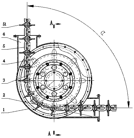
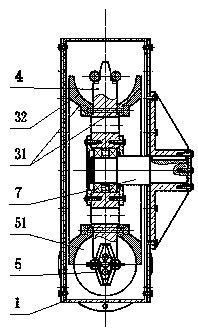
[0015] exist figure 1 and figure 2 In the non-contact corner box shown, the box shell 1 is a circular shell member, and the tube chain sprocket 4 corresponding to the tube chain 5 is arranged in the box shell 1, and the tube chain sprocket 4 passes through the bearing The rotation is supported on the sprocket shaft 7, the sprocket shaft 7 is fixedly connected to the shaft seat, and the shaft seat is fixedly connected to the box shell 1, so that the pipe chain sprocket 4 is rotatably supported on the box shell 1 through the sprocket shaft 7; the box shell 1 Feed pipe 6 and discharge pipe 2 are arranged on the circumference of the pipe chain 5, the feed pipe 6 and discharge pipe 2 are circular pipes corresponding to the circular scraper 51 on the pipe chain 5, the feed pipe 6 and the discharge pipe 2 The extended end of the feed pipe 2 is provided with a connecting flange connected to the conveying pipeline; the center line of the feed pipe 6 and the center line of the dischar...


PUM


Abstract

The invention discloses a non-contact type corner box. The non-contact type corner box comprises a box shell, a pipe chain, a feeding pipe and a discharging pipe; a pipe chain wheel corresponding to the pipe chain is arranged inside the box shell and supported on the box shell rotationally through a chain wheel shaft; an annular trough plate is arranged on the tooth portion of the pipe chain wheel; the center line of the annular trough plate and the center line of the pipe chain wheel are located on the same straight line; and the section of a groove of the annular trough plate is matched witha scraper blade on the pipe chain in shape. By adoption of the non-contact type corner box, contact and friction between the conveying pipe chain and a conveying pipeline can be avoided, the workingis stable and reliable, and the service life is long.

Description

technical field [0001] The invention relates to a conveying machine, in particular to a corner device of a pipe chain conveying machine. Background technique [0002] The pipe chain conveyor uses the pipe chain scraper in the closed conveying pipeline as the conveying member to drive the material to move along the pipe. The pipe chain scraper is installed on the conveying pipe chain, and the conveying pipe chain corresponds to the conveying pipe. The whole pipe chain conveyor forms An annular channel, with a material inlet and an outlet on the circular conveying channel. The pipe chain conveyor has a compact structure and takes up little space. It can change the conveying direction in three dimensions, and the material is in a relatively closed conveying pipeline during the conveying process. Therefore, it has been widely used in many occasions that require sealing, cleanliness, and environmental protection. However, while the pipe chain conveyor can adapt to the three-dimen...

Claims


Application Information

Patent Timeline
IPC IPC(8): B65G19/20B65G19/22B65G19/28
CPCB65G19/20B65G19/22B65G19/28
Inventor 黄俊超李鹏阳黄美华武珊珊刘丹梅
Owner JINGSU HUALIANG MACHINERY
Learn More