Method for constructing stiff supporting dome structure

A construction method and tooling cable technology are applied in the dome roof structure, arch structure, building components and other directions, which can solve the problems of increasing construction difficulty, tension asymmetry, and construction trouble.

Inactive Publication Date: 2013-04-24
BEIJING UNIV OF TECH
View PDF3 Cites 12 Cited by
  • Summary
  • Abstract
  • Description
  • Claims
  • Application Information

AI Technical Summary

Problems solved by technology

[0003] (1) The staff need to work at heights to complete the installation and tensioning of the cable dome structure, which not only increases the difficulty of construction but also makes it difficult to guarantee the personal safety of the staff
[0004] (2) The layer-by-layer tensioning method is adopted in the tensioning process of the cable dome structure, which increases the difficulty of construction tensioning, and it is difficult to control the whole construction process, and it is very difficult to meet

Method used


Image

  • Method for constructing stiff supporting dome structure
  • Method for constructing stiff supporting dome structure
  • Method for constructing stiff supporting dome structure

Examples


Embodiment 1

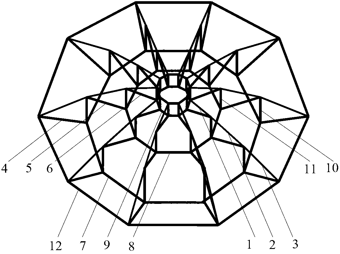
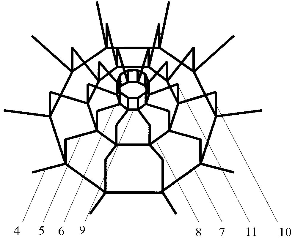
[0033] Such as figure 1 , figure 2 , image 3 , Figure 4 , Figure 5 and Figure 6 As shown, the construction forming process of this embodiment is as follows: the first step is to install the center inner pull ring 9, connect the upper end of the inner ridge cable 1 with the upper ear plate 13 of the center inner pull ring 9, and install and connect the inner ridge cable 1 and the middle ridge cable. 2. The outer ridge cable 3 is connected with the ring beam 12 through the tooling cable. The lower end of the inner oblique rod 6 is connected with the lower ear plate 14 of the center inner pull ring 9 . which is figure 1 , Figure 5 and Figure 6The central inner pull ring, the inner notochord 1, the middle notochord 2, the outer notochord 3 and the inner oblique rod 6. The specific installation method is as follows: first set up the operation platform, then install the welding center inner pull ring 9 at the central position of the center site, correspond the ear pl...

Embodiment 2

[0040] Such as figure 1 , Figure 5 , Figure 6 and Figure 7 As shown, the construction method of this embodiment is the same as that of Embodiment 1, except that the outer contour lines of the outer ring rod 7, the inner ring rod 8 and the ring beam 12 are elliptical.

Embodiment 3

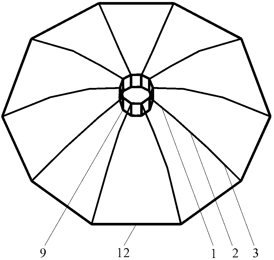
[0042] Such as figure 1 , Figure 5 , Figure 6 and Figure 8 As shown, the construction method of this embodiment is the same as that of Embodiment 1, except that the outer contour of the ring beam 12 is polygonal. Outlines of the outer ring rod 7, the inner ring rod 8 and the central inner pull ring 9 are all polygonal.


PUM


Abstract

The invention discloses a method for constructing a stiff supporting dome structure, and relates to the field of buildings. The method for constructing the stiff supporting dome structure includes firstly mounting an inner central draw ring and ridge ropes; secondly, mounting inner ring rods, and sequentially mounting inner sway rods and middle struts from top to bottom according to nodes; thirdly, mounting outer ring rods, integrally tensioning and lifting outer ridge ropes and tool ropes of middle sway rods, and mounting the middle sway rods and outer struts; fourthly, integrally tensioning and lifting the outer ridge ropes and tool ropes of outer sway rods and connecting the outer ridge ropes and the outer sway rods with ring beams; fifthly, tensioning the outer ridge ropes so that the appearance of a structure reaches design requirements; and sixthly, laying films to complete construction. The method for constructing the stiff supporting dome structure has the advantages that characteristics such as easiness in positioning of rods of the structure are sufficiently utilized, and the structure is integrally lifted and symmetrically mounted sequentially from inside to outside and from top to bottom according to the nodes and is tensioned and formed at one step; the rods are mounted on the ground or on an operation platform, so that aerial operation is avoided; and the rods are constantly lifted, and are prevented from being tensioned and released repeatedly.

Description

technical field [0001] The invention relates to a construction method of a rigidly supported dome structure in the construction field. Background technique [0002] The cable dome structure is a prestressed space structure composed of cables, rods and membranes. It has been favored by architects since it came out. However, due to the structural characteristics of the cable dome structure itself, there are many technical difficulties. For example, the positioning of the rod is difficult, the initial stiffness of the rod is low, and the construction is difficult. Therefore, many new prestressed spatial structures based on cable dome structures have emerged, such as stiffly braced dome structures. The upper layer of the rigidly supported dome structure is a cable net system, and the lower layer is a rigid rod system, that is, the lower cables of the cable dome structure are replaced with high-strength steel rods to enhance the rigidity of the rods and the overall rigidity of ...

Claims


Application Information

Patent Timeline
IPC IPC(8): E04B1/32
Inventor 薛素铎高占远李雄彦
Owner BEIJING UNIV OF TECH
Why Eureka
Try Eureka