Optical switch matrix and control method thereof

An optical switch matrix and optical signal technology, applied in the field of optical communication, can solve the problems of large PDL and DGD

Active Publication Date: 2018-03-13
HUAWEI TECH CO LTD
View PDF15 Cites 2 Cited by
  • Summary
  • Abstract
  • Description
  • Claims
  • Application Information

AI Technical Summary

Problems solved by technology

[0005] The embodiment of the present invention provides an optical switch matrix and its control method, which is used to solve the problem in the prio

Method used


Image

  • Optical switch matrix and control method thereof
  • Optical switch matrix and control method thereof
  • Optical switch matrix and control method thereof

Examples


Embodiment Construction

[0087] In order to make the purpose, technical solutions and advantages of the embodiments of the present invention clearer, the technical solutions in the embodiments of the present invention will be clearly and completely described below in conjunction with the drawings in the embodiments of the present invention. Obviously, the described embodiments It is a part of embodiments of the present invention, but not all embodiments. Based on the embodiments of the present invention, all other embodiments obtained by persons of ordinary skill in the art without creative efforts fall within the protection scope of the present invention.

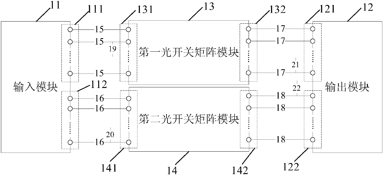
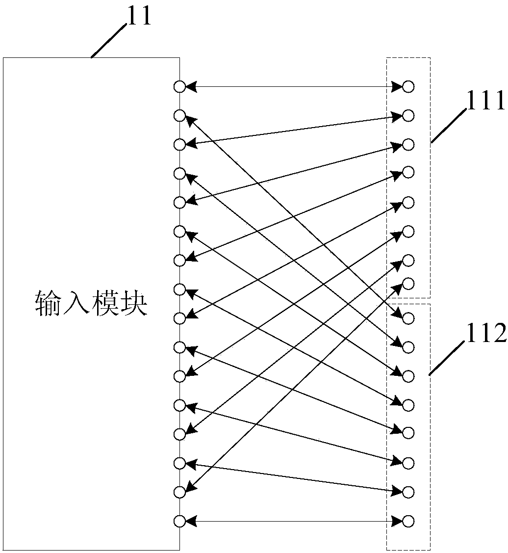
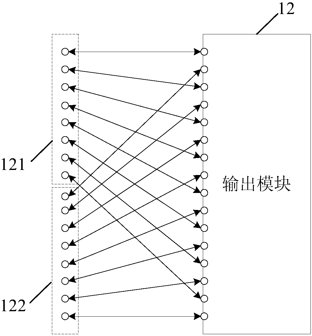
[0088] The present invention can be applied in an optical switch matrix, and the optical switch matrix is ​​used for performing wavelength selection, routing selection and other processing on optical signals in an optical communication network. Wherein, the optical signals in the optical communication network may include single-mode optical signal...


PUM


Abstract

An embodiment of the invention provides an optical switch matrix and a control method thereof. Through transmitting a first single-mode optical signal and a second single-mode optical signal in an optical communication network through waveguides with the same length in a first mode in the optical switch matrix and processing by the same device, and performing one-time mode conversion, a problem ofrelatively high PDL and DGD of the optical signal in the optical network through processing by the optical switch matrix is settled. Furthermore, through arranging a first crossed waveguide, a secondcrossed waveguide, a third crossed waveguide and a fourth crossed waveguide, a number difference between the crossed waveguides on different waveguides is reduced, thereby further reducing the PDL.

Description

technical field [0001] Embodiments of the present invention relate to the field of optical communications, and in particular to an optical switch matrix and a control method thereof. Background technique [0002] With the rapid development of optical communication systems and the introduction of dense wavelength division multiplexing technology, the optical switch matrix has become a crucial component in the field of optical communication, which can realize important functions such as routing selection, wavelength selection, and optical cross-connection. [0003] In the prior art, optical signals in an optical communication network may include single-mode optical signals of different modes. Generally, the optical switch matrix is ​​mainly composed of waveguides and devices formed by the waveguides, where the devices may be, for example, optical switches, polarization rotator beam splitters (PSR, Polarization Splitter Rotator) and the like. Due to the different lengths of th...

Claims


Application Information

Patent Timeline
IPC IPC(8): G02B6/35G02B6/26G02B6/27
CPCG02B6/266G02B6/27G02B6/2773G02B6/354H04Q11/00
Inventor 赵飞
Owner HUAWEI TECH CO LTD
Why Eureka
Try Eureka