Control circuit and working method thereof
A technology of control circuit and working method, applied in the direction of control/adjustment system, adjustment of electrical variables, instruments, etc., can solve the problems of increasing the difficulty of production control, inability to apply potentiometers, and the knob control method is easily affected by the environment, etc.
- Summary
- Abstract
- Description
- Claims
- Application Information
AI Technical Summary
Problems solved by technology
Method used
Image
Examples
Embodiment 1
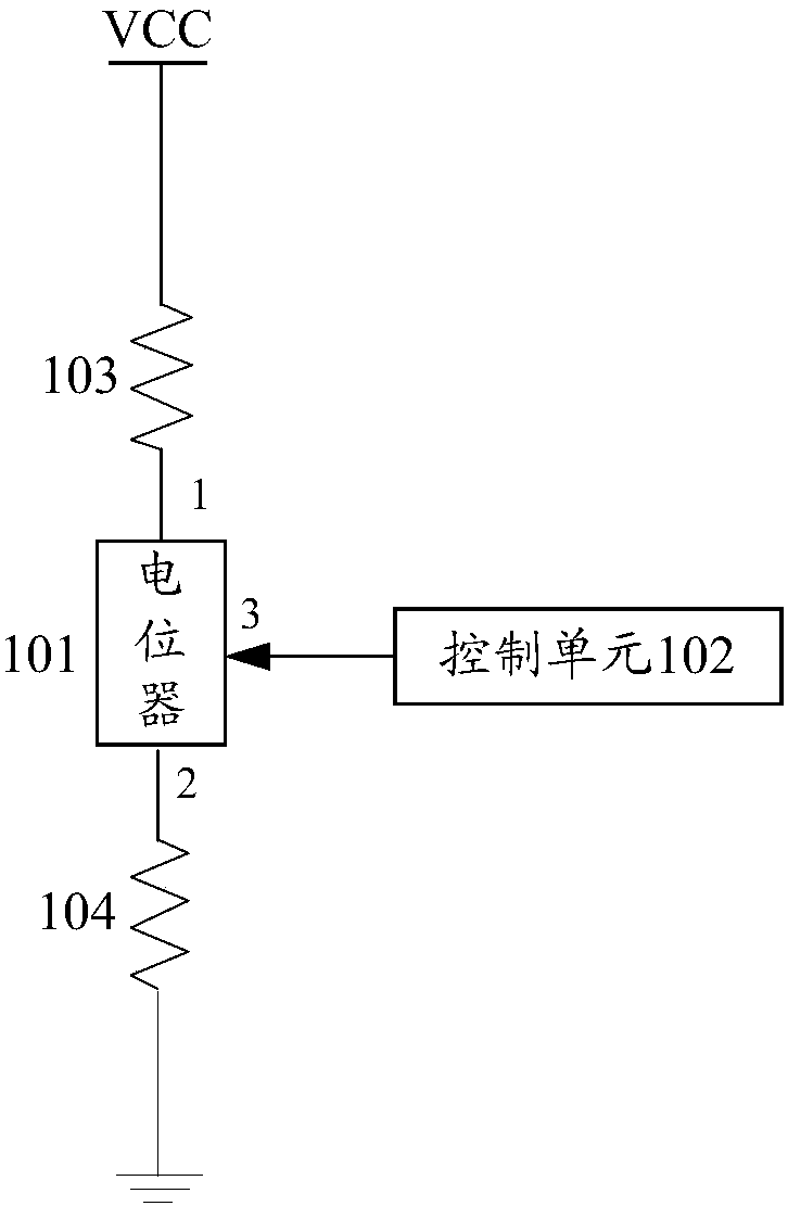
[0056] See figure 1 , Which shows a control circuit 10 provided by an embodiment of the present invention, such as figure 1 As shown, the control circuit 10 may include: a potentiometer 101, a control unit 102, a pull-up resistor 103, and a pull-down resistor 104; it is understandable that the complete control circuit also needs to include a voltage for the normal operation of the control circuit The power supply VCC and the ground GND are not repeated in this embodiment.
[0057] in figure 1 In the control circuit shown, the first fixed terminal 1 of the potentiometer 101 is connected to the pull-up resistor 103; the second fixed terminal 2 of the potentiometer 101 is connected to the pull-down resistor 104; the potentiometer The sliding end 3 of 101 is connected to the control unit 102;
[0058] The control unit 102 is configured to obtain the voltage value range of the potentiometer 101 in a working state;
[0059] And, the voltage step value corresponding to each gear is determi...
Embodiment 2
[0087] Based on the same technical idea as the foregoing embodiment, see image 3 , Which shows a working method of a control circuit provided by an embodiment of the present invention. The method can be applied to the control circuit described in the above embodiment. The control circuit may include: a potentiometer, a control unit, a pull-up resistor, and A pull-down resistor; wherein the first fixed end of the potentiometer is connected to the pull-up resistor; the second fixed end of the potentiometer is connected to the pull-down resistor; the sliding end of the potentiometer is connected to the control unit Connection; the working method of the control circuit can include:
[0088] S301: The control unit obtains the voltage value range in the working state of the potentiometer;
[0089] S302: The control unit determines the voltage step value corresponding to each gear within the voltage value range according to the preset number of gears; wherein the voltage step value corre...
Embodiment 3
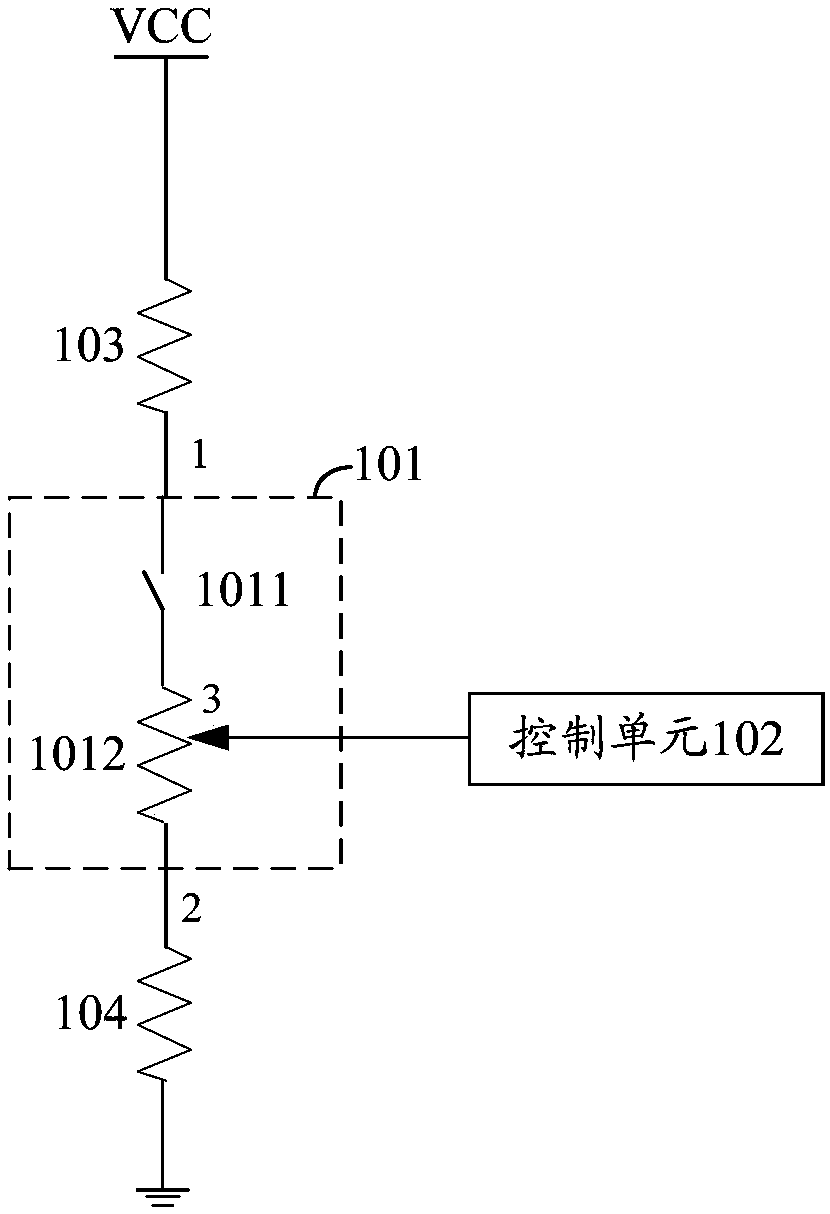
[0105] For example two, image 3 The specific control circuit shown is an example, see Image 6 The detailed process of the working method of the control circuit may include:
[0106] S601: After power-on, the control unit detects the port voltage of the potentiometer;
[0107] Understandably, such as image 3 As shown, the control unit can detect the port voltage of the potentiometer sliding end;
[0108] S602: The control unit detects whether the switch is closed; if so, go to S603; otherwise, go to S601 to continue to detect the port voltage of the potentiometer;
[0109] S603: When the switch is closed, the control unit samples the voltage V1 at the sliding end of the potentiometer;
[0110] S604: The control unit obtains the wiper voltage V2 at the maximum stroke of the potentiometer according to the voltage V1 at the wiper end of the potentiometer when the switch is closed;
[0111] S605: The control unit determines the voltage value range in the working state of the potentiometer ...
PUM
 Abstract
Description
Claims
Application Information
 - R&D
- Intellectual Property
- Life Sciences
- Materials
- Tech Scout
- Unparalleled Data Quality
- Higher Quality Content
- 60% Fewer Hallucinations
Browse by: Latest US Patents, China's latest patents, Technical Efficacy Thesaurus, Application Domain, Technology Topic, Popular Technical Reports.
© 2025 PatSnap. All rights reserved.Legal|Privacy policy|Modern Slavery Act Transparency Statement|Sitemap|About US| Contact US: help@patsnap.com


