Shield flat cable
A flat cable and shielding film technology, applied in the direction of flat/ribbon cables, power cables, insulated cables, etc., can solve the problems of different height positions, unstable connection between ground conductors and ground pads, etc., and achieve the effect of reliable connection
- Summary
- Abstract
- Description
- Claims
- Application Information
AI Technical Summary
Problems solved by technology
Method used
Image

Examples
no. 1 Embodiment approach
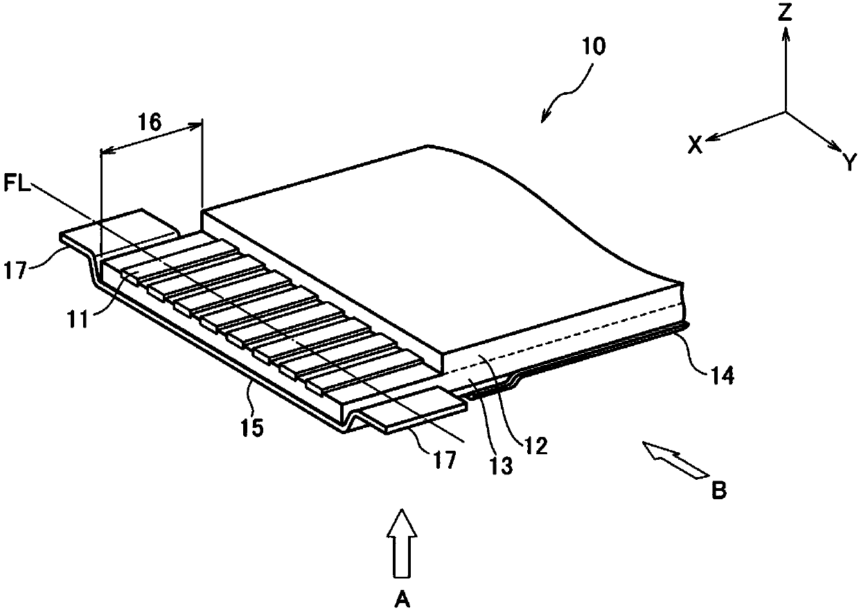
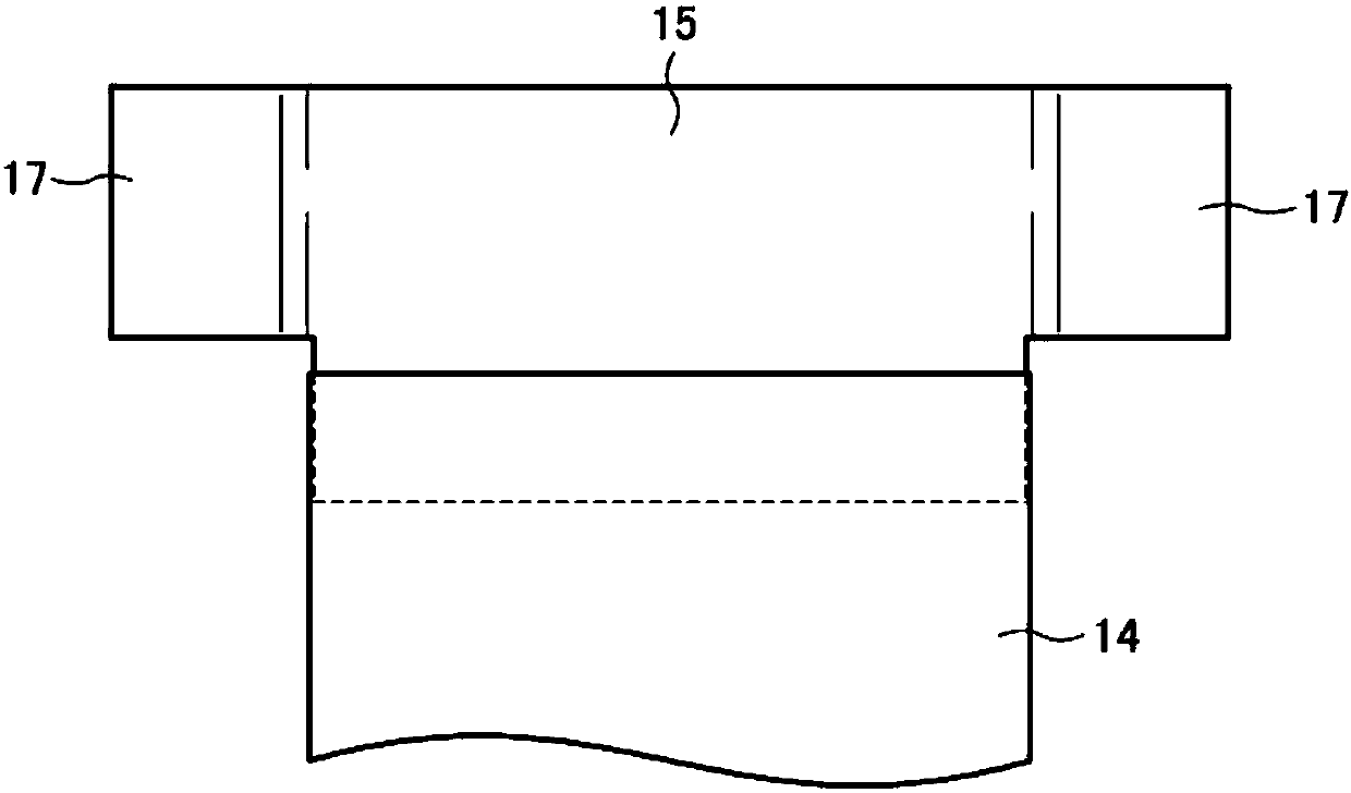
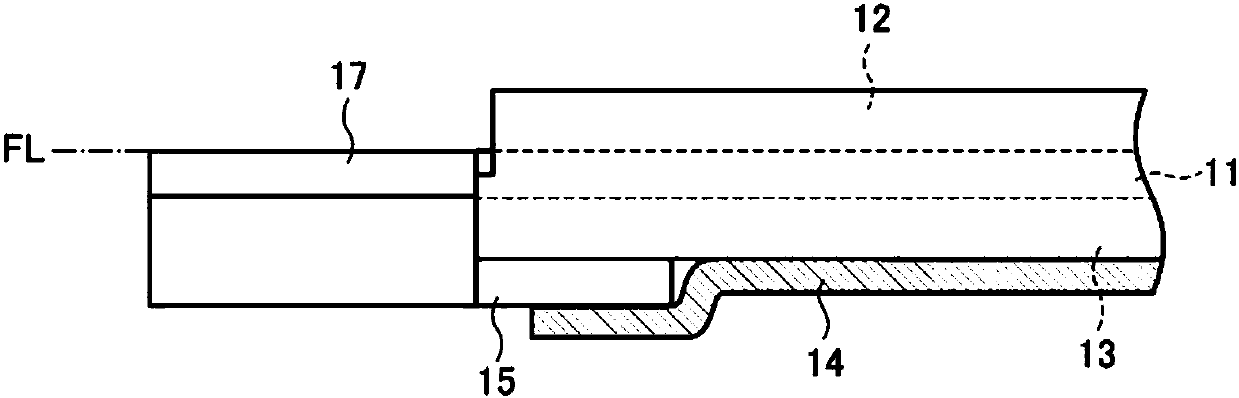
[0038] figure 1 It is a perspective view showing the outline of the shielded flat cable according to the first embodiment of the present invention. figure 2 From figure 1 The rear view of the arrow A observed. image 3 From figure 1 Side view of arrow B observed. Figure 4 is a schematic cross-sectional view showing the masking film. Figure 5 It is a perspective view for explaining the connection between the shielded flat cable and the board according to the first embodiment of the present invention.
[0039] Such as figure 1 As shown, the shielded flat cable 10 according to this embodiment is composed of a plurality of flat conductors 11 , insulating films 12 and 13 , a shielding film 14 , and a ground conductor 15 . The shielded flat cable 10 is a flat cable in which, for example, a plurality of flat conductors 11 having a flat cross section and extending in the X-axis direction are arranged in parallel with the Y-axis direction, and the flat conductors 11 and the fl...
no. 2 Embodiment approach
[0054] Next, a second embodiment of the shielded flat cable of the present invention will be described with reference to the drawings. Figure 6 It is a perspective view showing the outline of the shielded flat cable according to the second embodiment of the present invention. Figure 7 From Figure 6 Posterior view of arrow C observed. Figure 8 From Figure 6 Side view of arrow D observed. and, Figure 9 From Figure 6 Cross-sectional view observed by arrow E. This embodiment differs from the first embodiment in the shape and arrangement of the ground conductor, and the other configurations are the same as those in the first embodiment, so only the different configurations will be described.
[0055] Such as Figure 7 and Figure 9 As shown, the ground conductor 25 of the shielded flat cable 20 according to the present embodiment is formed in a U-shape by a thin plate of conductive metal foil, and extends along the longitudinal direction of the flat conductor 11 outs...
no. 3 Embodiment approach
[0061] Next, a third embodiment of the shielded flat cable of the present invention will be described with reference to the drawings. Figure 11 It is a perspective view showing the outline of the shielded flat cable according to the third embodiment of the present invention. Figure 12 From Figure 11 Posterior view of arrow C observed. Figure 13 From Figure 11 Side view of arrow D observed. Compared with the second embodiment, this embodiment differs from the second embodiment in that the end of the flat conductor is different, and the same as the first embodiment, the ground conductor is located between the insulating film and the shielding film, and the other structures are the same as the second embodiment, so only the difference structure is described.
[0062] Such as Figure 11 to Figure 13 As shown, in this embodiment, all surfaces of the flat conductor 11 may be exposed at the end of the shielded flat cable 40 . All surfaces of the flat conductor 11 can be ex...
PUM
| Property | Measurement | Unit |
|---|---|---|
| Thickness | aaaaa | aaaaa |
| Width | aaaaa | aaaaa |
| Thickness | aaaaa | aaaaa |
Abstract
Description
Claims
Application Information
 - Generate Ideas
- Intellectual Property
- Life Sciences
- Materials
- Tech Scout
- Unparalleled Data Quality
- Higher Quality Content
- 60% Fewer Hallucinations
Browse by: Latest US Patents, China's latest patents, Technical Efficacy Thesaurus, Application Domain, Technology Topic, Popular Technical Reports.
© 2025 PatSnap. All rights reserved.Legal|Privacy policy|Modern Slavery Act Transparency Statement|Sitemap|About US| Contact US: help@patsnap.com