Terminal and connector

Inactive Publication Date: 2006-08-03
YAZAKI CORP
View PDF10 Cites 12 Cited by
  • Summary
  • Abstract
  • Description
  • Claims
  • Application Information

AI Technical Summary

Benefits of technology

[0027] It is therefore an object of the present invention to provide a compact design of a press-contacting metal terminal and a compact design of a press-contacting conn

Problems solved by technology

And besides, there is encountered a problem that the strength of the press-contacting blades decreases with the compact design of the press-contacting metal terminal, so that the press-contacting force is lowered.
Therefore, there are occasions when the configuration of the connector is limited by the direction of removal of the molded connector from a mold.
Therefore, because of its structure, the mold need to include a slide mold, and therefore is complicated in structure.
As a result, there was a disad

Method used


Image

  • Terminal and connector
  • Terminal and connector
  • Terminal and connector

Examples


first embodiment

[0093] a press-contacting metal terminal and a press-contacting connector of the invention, will now be described in detail with reference to the accompanying drawings.

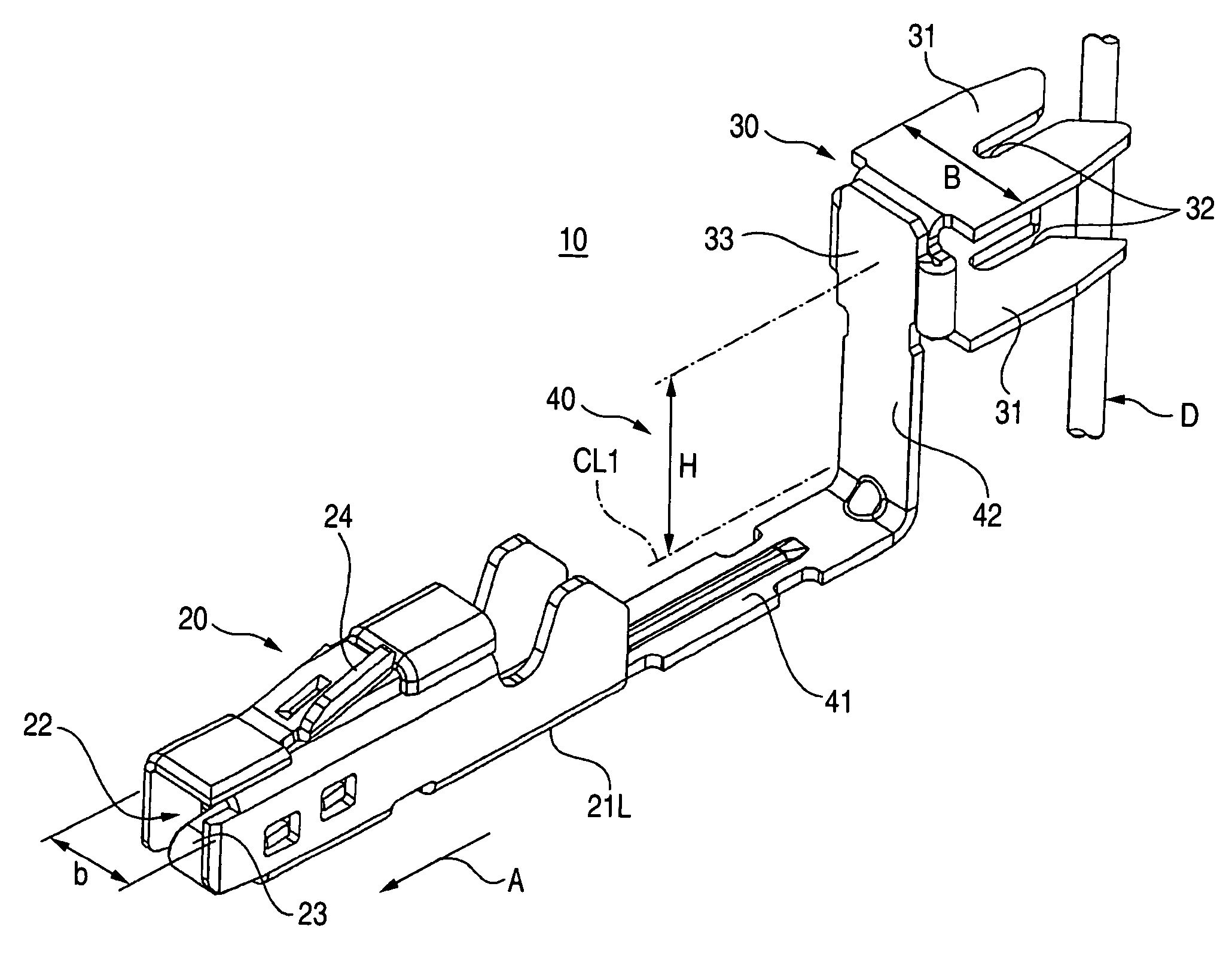
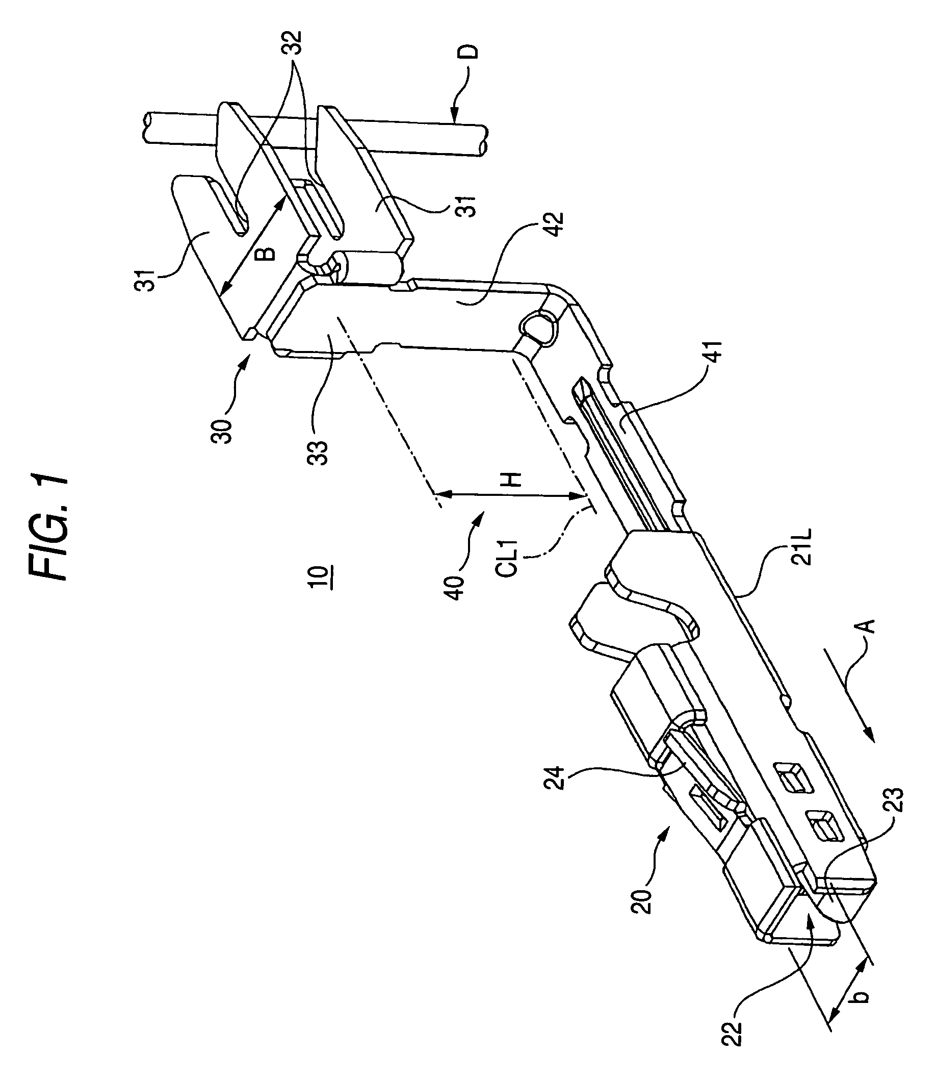
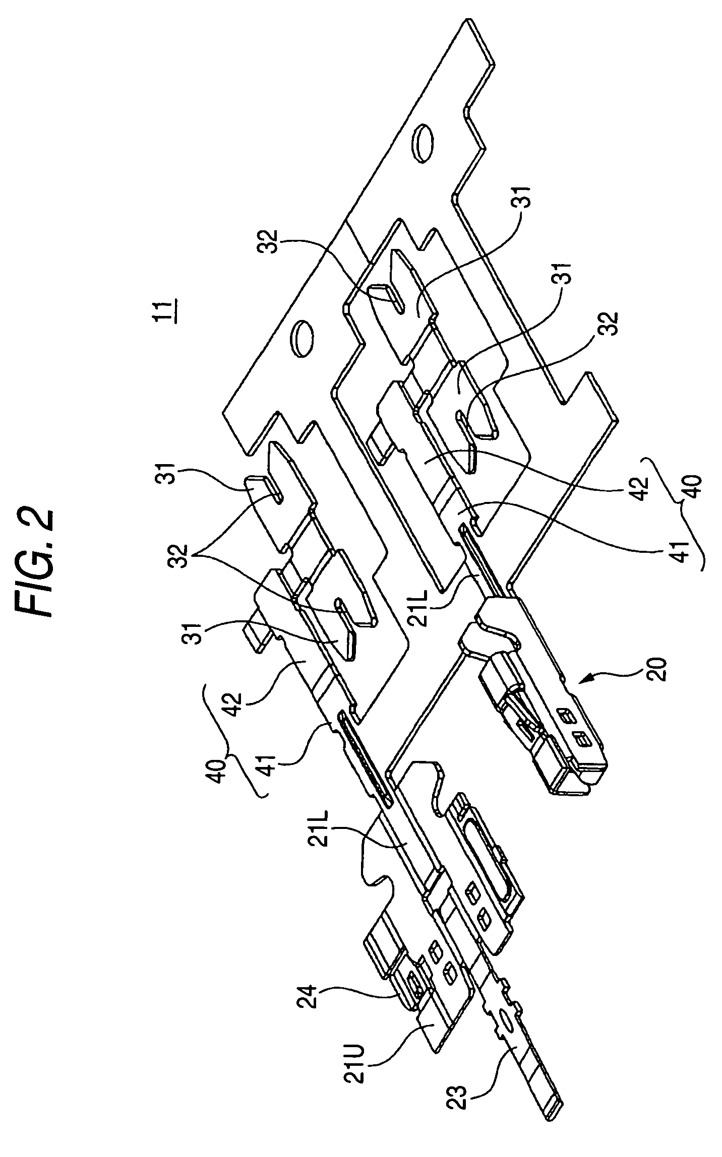
[0094]FIG. 1 is a perspective view showing the whole of the first embodiment of the press-contacting metal terminal of the invention, and FIG. 2 is a developed view of the press-contacting metal terminal of FIG. 1.

[0095] As shown in FIG. 1, the press-contacting metal terminal 10 of this embodiment includes a terminal connecting portion 20 of a tubular shape formed at one end of a base plate 21L formed of an electrically-conductive metal sheet, and a wire press-contacting portion 30 formed at the other end of the base plate 21L, and a wire D can be press-contacted with this wire press-contacting portion 30 in such a manner that the wire D extends in a direction perpendicular to a terminal fitting direction (in a direction of arrow A in FIG. 1).

[0096] The wire press-contacting portion 30 and the terminal connecting po...

second embodiment

[0139] Next, the present invention will now be described in detail with reference to the drawings.

[0140] As shown in FIGS. 13 and 14, the connector 121 of this embodiment includes a housing 123 molded of a synthetic resin, the plurality of terminals 125 received in the housing 123, and a wire retaining member (retainer) which will be described later.

[0141] As shown in FIG. 15, the terminal 125 is formed by bending an electrically-conductive sheet material, and this terminal 125 has a box-like electrical contact portion 127 formed at its front portion. A resilient contact piece portion 129 for contact with a mating male terminal (not shown) is formed by bending, and is received within the electrical contact portion 127.

[0142] A retaining piece portion 131 is formed by bending on an upper outer surface of the electrical contact portion 127, and extends toward the rear end of the terminal in a slanting manner. When the terminal 125 is inserted into the housing 123, the retaining piec...


PUM


Abstract

A connector includes a plurality of terminals and a connector housing, receiving the terminals. Each of the terminals includes a terminal connecting portion, having a tubular shape, and receiving a mating terminal, a wire press-contacting portion including a press-contacting blade for press-contacting a wire, and the press-contacting blade having a blade width larger than a width of the terminal connecting portion, and an interconnecting portion, connecting the terminal connection portion and a wire press-contacting portion. A press-contacting direction in which the wire is press-contacted with the wire press-contacting portion is parallel to a terminal fitting direction of the terminal connecting portion. The terminal connecting portions of the terminals are received in the connector housing in parallel so that the press-contacting blades are arranged in a staggered manner. Also, a connector includes a housing and a terminal received in the housing. The terminal includes a wire connecting portion which connects a wire and an extension portion which is extended from the wire connecting portion. The extension portion has a conductive portion which is formed in a direction intersecting a direction in which the terminal is inserted into the housing. The housing has an exposure hole through which at least part of the conductive portion is exposed to an exterior.

Description

BACKGROUND OF THE INVENTION [0001] This invention relates to a terminal and a connector, and more particularly to an improved press-contacting terminal having a wire press-contacting portion with which a wire is press-contacted in such a manner that the wire extends in a direction perpendicular to a terminal fitting direction. [0002] Also, this invention relates to a connector having a housing in which a plurality of terminals, connected respectively to wires, are received, and more particularly to such a connector in which an electrical connection of each terminal can be checked by bringing a probe of a tester into contact with the terminal from the outside of the housing. [0003] One related press-contacting metal terminal is formed by cutting and bending an electrically-conductive metal sheet, and this metal terminal has a narrow, elongated box-like body having a uniform width over an entire length thereof (see, for example, JP-A-10-294138, especially, pages 2 and 3, FIG. 1). [000...

Claims


Application Information

Patent Timeline
IPC IPC(8): H01R4/24H01R13/11H01R13/432H01R13/506H01R43/01
CPCH01R4/245H01R13/11H01R13/432H01R13/506H01R43/01H01R2201/20H01R4/2452Y10S439/912
Inventor TASHIRO, HARUNORIFUKUDA, MASARU
Owner YAZAKI CORP
Why Eureka
Try Eureka