

LED lamp circuit board for integrating light source and power supply and manufacture method thereof
A technology for LED lamps and manufacturing methods, which is applied in the field of LED lamp circuit boards and its manufacturing, and can solve the problems that the width cannot meet the horizontal placement of light source boards, the low product qualification rate, and the short length of the placement machine, so as to achieve fast and simple production and high product quality The effect of high pass rate and high production efficiency
- Summary
- Abstract
- Description
- Claims
- Application Information
AI Technical Summary
Problems solved by technology
Method used
Image

Examples
Embodiment 1
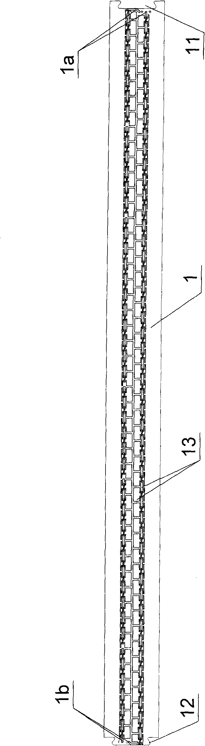
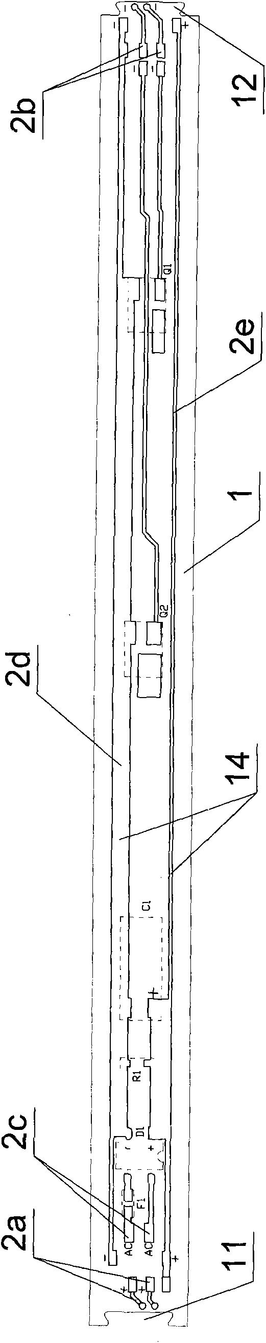
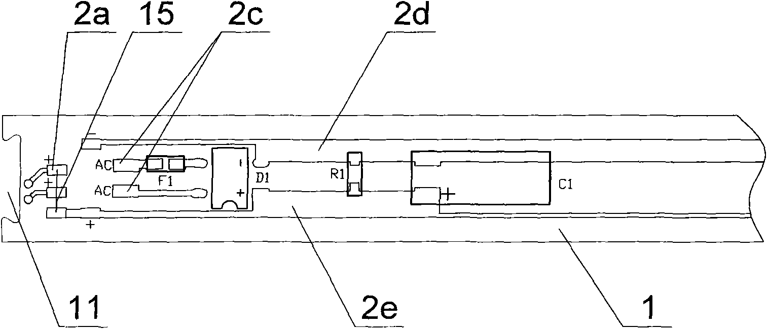
[0041] Such as Figure 1 to Figure 5 , Figure 7 , Figure 8As shown, the LED lamp circuit board integrating light source and power supply in this embodiment includes two module unit boards 1, the module unit boards 1 are fixedly connected, and the front side of the module unit board 1 is provided with a The LED chip 2 and the metal layer 13 that dissipates heat and forms an electrical connection between the LED chips 2, and the back side of the module unit board 1 is provided with a power supply line 14 made of conductive metal for welding circuit elements and forming a circuit. The power lines 14 of the module unit board 1 that are fixedly connected are electrically connected by jumpers, and the two ends of the module unit board 1 are respectively provided with grooves 11 and bumps 12, and the grooves 11 and The size and shape of the bump 12 are compatible, the groove 11 and the bump 12 are dovetail-shaped, and the connection and fixing are reliable. The module unit board ...
Embodiment 2
[0045] Such as Figure 1 to Figure 4 , Figure 6 , Figure 7 , Figure 9 ~ Figure 11 As shown, this embodiment is the same as the wiring of the metal layer 13 and the power line 14 of the modular unit board 1 in Embodiment 1, that is, the bare board is the same. In addition, the LED on the front side of the modular unit board 1 The number and arrangement of the chips 2 are also exactly the same, the difference is that in this embodiment, the two LED chips 2 on the module unit board 1 are connected in parallel to form a group, and the two groups are connected in parallel again, that is, there are four LED chips 2 in total. The LED chips 2 are connected in parallel, and each channel has 48 LED chips 2. The rated power of this embodiment is also 12W, and it is applied to a 110V AC power supply as lighting. Correspondingly, there are two groups of four LED chips in this embodiment. The constant current source MOS devices Q1, Q2 are respectively connected in series with 48 LED c...
Embodiment 3
[0049] Such as Figure 12 As shown, the difference between this embodiment and Embodiment 1 is: in this embodiment, two ends of each of the modular unit boards 1 are respectively provided with two of the grooves 11 and two of the protrusions 12 , the groove 11 and the protrusion 12 are both circular, and the connection and fixing are reliable.
[0050] The remaining features of this embodiment are the same as those of Embodiment 1.
PUM
 Abstract
Description
Claims
Application Information