Aircraft turbofan engine

a turbofan engine and aircraft technology, applied in the field of aircraft turbofan engines, can solve the problems of generating considerable noise, negatively affecting therefore that of the aircraft carrying, and achieve the effects of improving the performance of the turbofan engine, reducing the noise of the shock cell, and reducing the noise of the cold stream

Active Publication Date: 2015-02-24
AIRBUS OPERATIONS (SAS)
View PDF16 Cites 0 Cited by
  • Summary
  • Abstract
  • Description
  • Claims
  • Application Information

AI Technical Summary

Benefits of technology

[0014]The projecting rounded boss provided by the present invention corresponds to a local reduction in the radius of curvature of said inner fan cowl and hence to an acceleration of the cold stream when passing over said boss, such that the speed of said cold stream changes locally to a supersonic value, thus giving rise to the first characteristic of the shockwave. Furthermore, on account of the curvature of this projecting rounded boss, said first characteristic of the shockwave can be relatively greatly inclined toward the rear with respect to the flow of the cold stream, with the result that the same can apply for the following characteristics. Thus, unlike the known turbofan engines in which the shockwave is formed by abrupt normal shocks, the shockwave in the improved turbofan engine according to the invention consists of oblique shocks resulting in smooth, progressive transitions with intermediate speed values between the supersonic speed zones and the subsonic speed zones. The speed of the cold stream thus tends to be made more uniform and there is a consequent improvement in the performance of the turbofan engine with a simultaneous reduction in the shock cell noise.
[0015]It will be noted that, by arranging a projecting boss on the inner fan cowl, the present invention takes a different approach from the prior art which, as referred to above, makes provision for the surface of this cowl to be as smooth as possible, without unevenness, in order to reduce as far as possible the performance losses owing to friction. In fact, the Applicant has found that, at the expense of a small performance loss due to the presence of the projecting rounded boss on the inner fan cowl, it is possible to enjoy a significant increase in turbofan engine performance by replacing the normal shocks of the prior art with the oblique shocks of the present invention.
[0016]The first characteristic, originating from said rounded boss, can meet up directly with the slip surface between said external aerodynamic flow and said cold stream and be reflected there. However, it is preferable for said first characteristic to meet the outer fan cowl in order to be reflected there in the form of the second characteristic, likewise inclined toward the rear, of said shockwave. Thus, the inclination of said second characteristic can be influenced by the curvature of said outer fan cowl at the location of the impact of said first characteristic. More advantageously still, in the latter case in which said first characteristic meets the outer fan cowl, provision is made to position said cold-stream outlet orifice at the location of this meeting point, thereby avoiding an excessive length for the cold-stream nozzle and thus allowing savings in terms of mass and drag. The second characteristic thus has its origin at the edge of said cold-stream outlet orifice.

Problems solved by technology

Such a shockwave having normal shocks not only generates considerable noise (known as “shock cell noise”) but also negatively impacts the performance of the turbofan engine and therefore that of the aircraft carrying it.

Method used


Image

  • Aircraft turbofan engine
  • Aircraft turbofan engine
  • Aircraft turbofan engine

Examples


Embodiment Construction

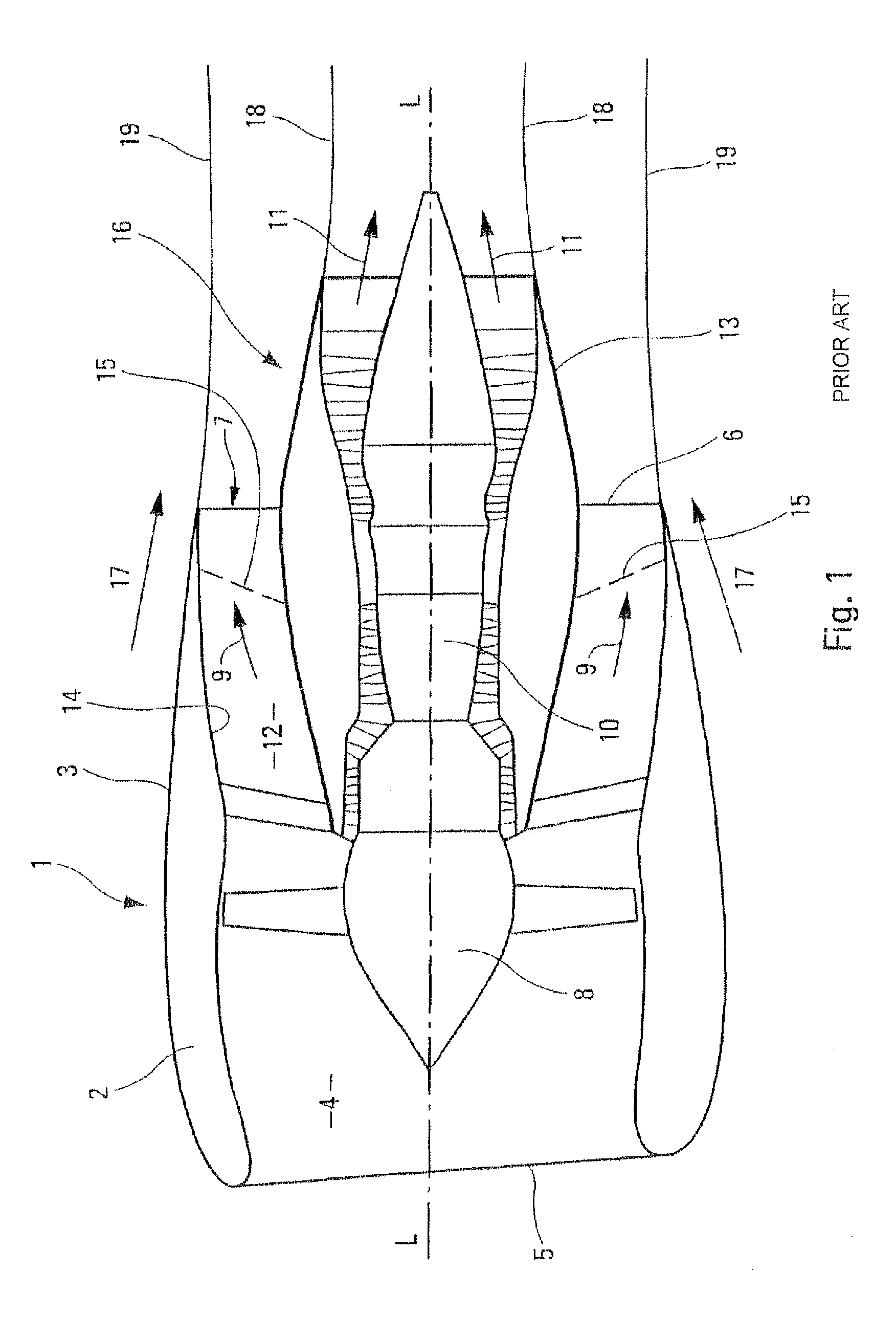
[0026]The turbofan engine 1, of longitudinal axis L-L, shown in FIG. 1, comprises a nacelle 2 bounded externally by an outer nacelle cowl 3.

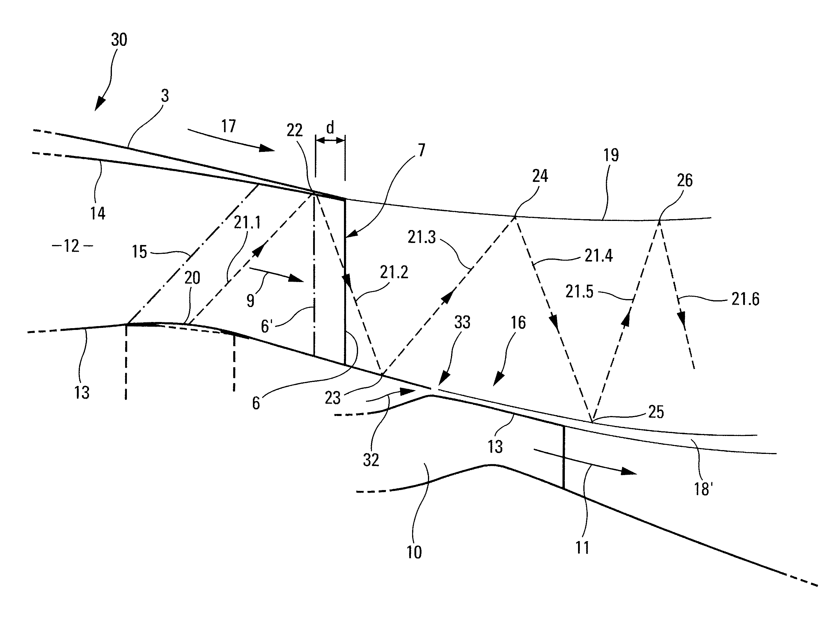
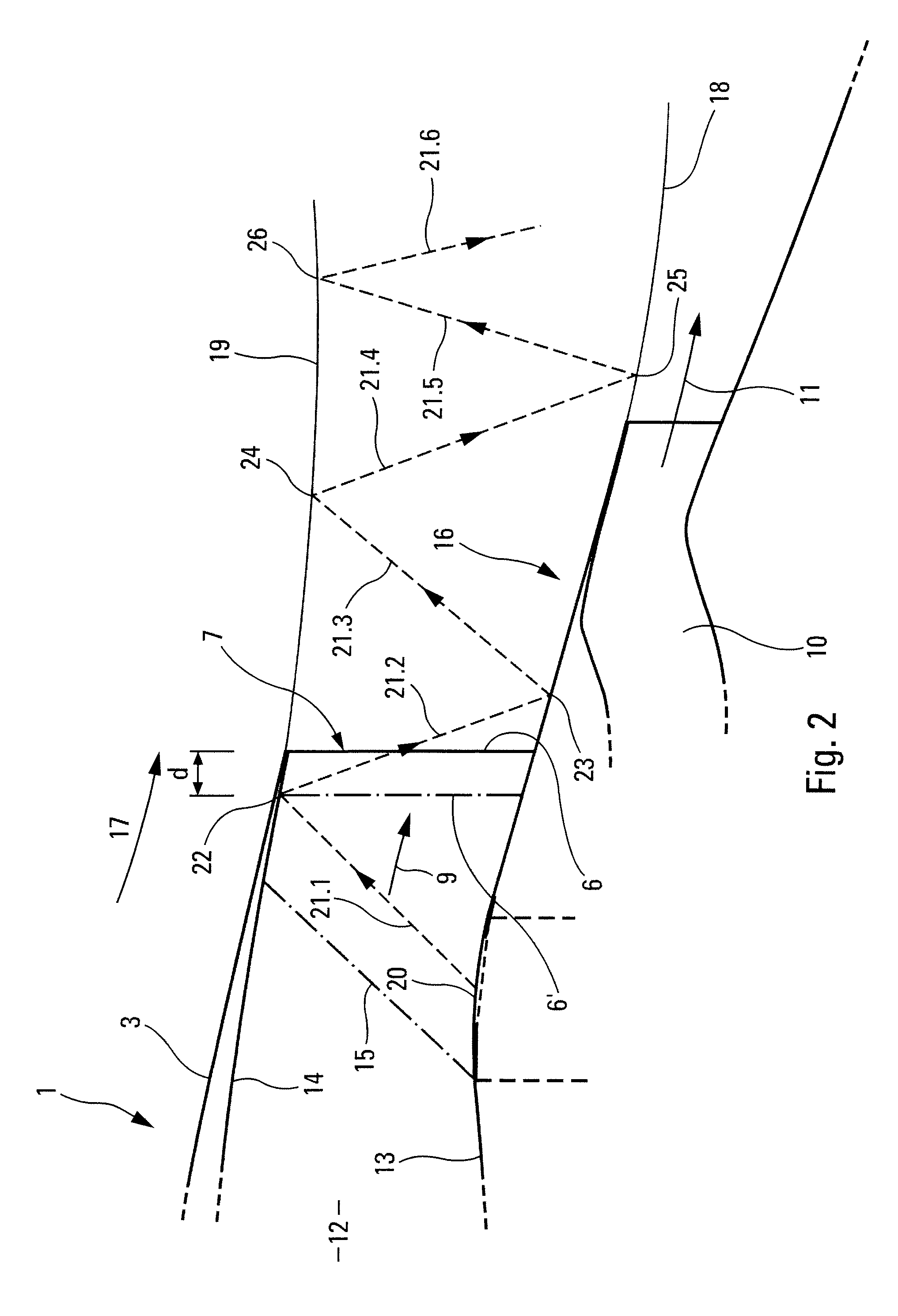
[0027]The nacelle 2 comprises, at the front, an air inlet 4 provided with a leading edge 5 and, at the rear, an air outlet orifice 6 provided with a trailing edge 7.

[0028]Inside said nacelle 2 are arranged:[0029]a fan 8 directed toward the air inlet 4 and able to generate the cold stream 9 for the turbofan engine 1;[0030]a central generator 10 comprising, in a known manner, low-pressure and high-pressure compressors, a combustion chamber and low-pressure and high-pressure turbines, and generating the hot stream 11 of said turbofan engine 1; and[0031]an annular cold-stream duct 12 formed around said central generator 10, between an inner fan cowl 13 arranged in the region of the central generator 10 and an outer fan cowl 14 arranged in the region of the outer nacelle cowl 3.

[0032]The inner and outer fan cowls 13 and 14 between them form a nozzle ...


PUM


Abstract

Disclosed is a turbofan engine for an aircraft. An inner fan cowl of the turbofan engine bounds an annular cold-stream duct proximate to the engine's central hot-stream generator, and an outer fan cowl bounds the annular cold-stream duct proximate to an outer nacelle cowl. An annular boss is provided along the inner fan cowl, with the annular boss having a rounded cross section that projects with respect to a smooth shape configuration of the inner fan cowl. The annular boss is configured to locally change speed of a cold stream flow in the annular cold-stream duct from a subsonic range to a supersonic range and to originate a first shockwave characteristic in a succession of shockwave characteristics, with the first shockwave characteristic being inclined from its origin toward the rear portion of the turbofan engine.

Description

FIELD OF THE INVENTION[0001]The present invention relates to improvements to turbofan engines for aircraft, said improvements making it possible to increase the performance of said turbofan engines, and hence of said aircraft, particularly during cruise flight.BACKGROUND OF THE INVENTION[0002]More specifically, the invention relates to turbofan engines, described for example in document WO 2006 / 123035, of the type comprising, around a longitudinal axis:[0003]a nacelle provided with an outer nacelle cowl and enclosing a fan generating the cold stream and a central generator generating the hot stream;[0004]an annular cold-stream duct formed around said central hot-stream generator;[0005]an outer fan cowl bounding said annular cold-stream duct in the region of said outer nacelle cowl;[0006]a cold-stream outlet orifice whose edge, which forms the trailing edge of said nacelle, is defined by said outer nacelle cowl and by said outer fan cowl converging toward one another until they meet ...

Claims


Application Information

Patent Timeline
Patent Type & Authority Patents(United States)
IPC IPC(8): F02K1/00F02K1/78F02K3/06
CPCF02K3/06F02K1/78F05D2210/30
Inventor CROSTA, FRANCKPRAT, DAMIENGROSSEIN, DAVID
Owner AIRBUS OPERATIONS (SAS)
Why Eureka
Try Eureka