Clamping device for an ophthalmic vision chart
A clamping device and eye chart technology, applied in medical science, eye testing equipment, diagnosis, etc., can solve problems such as simple inflexibility, different sizes, and inability to test vision
- Summary
- Abstract
- Description
- Claims
- Application Information
AI Technical Summary
Problems solved by technology
Method used
Image
Examples
Embodiment 1
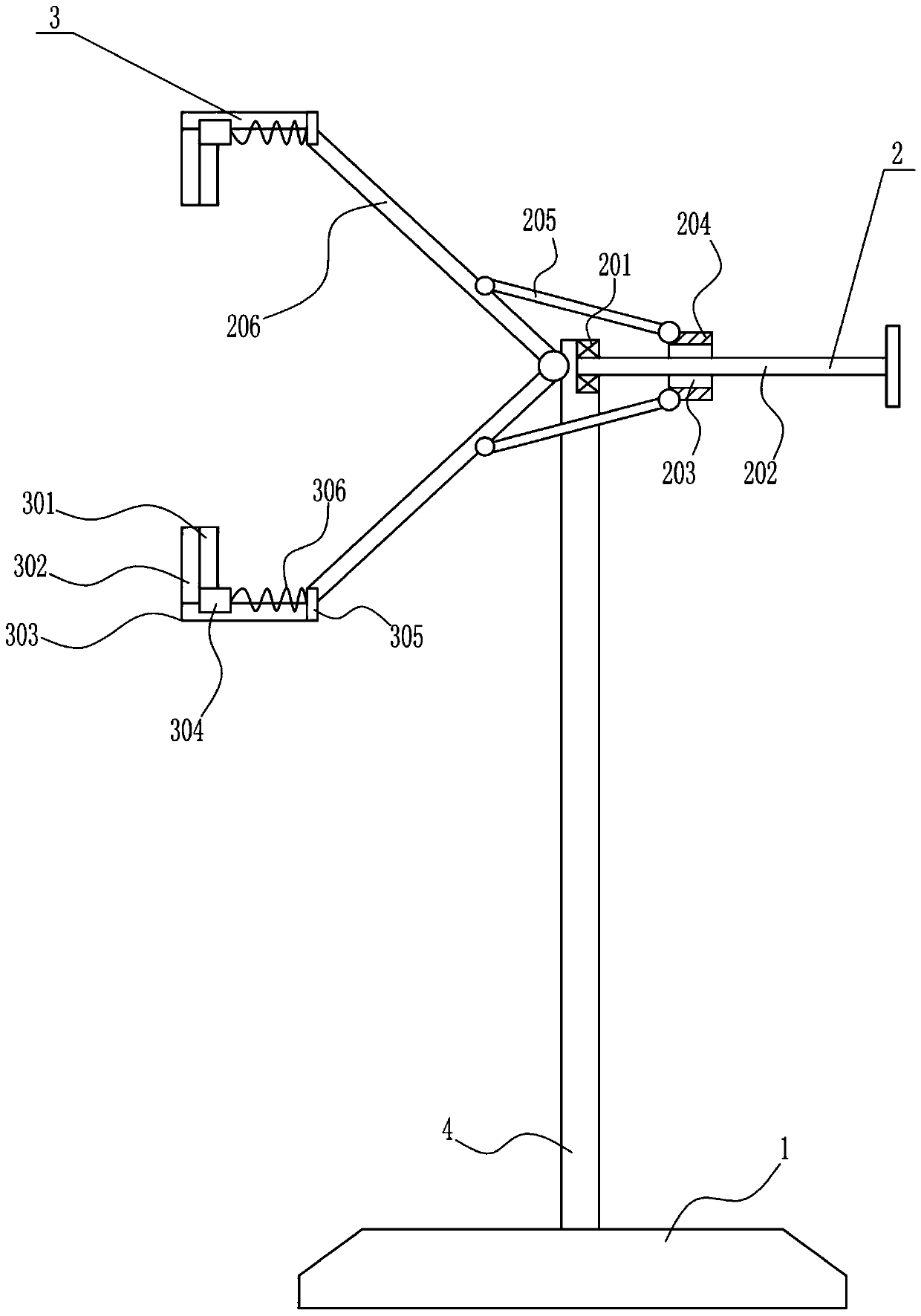
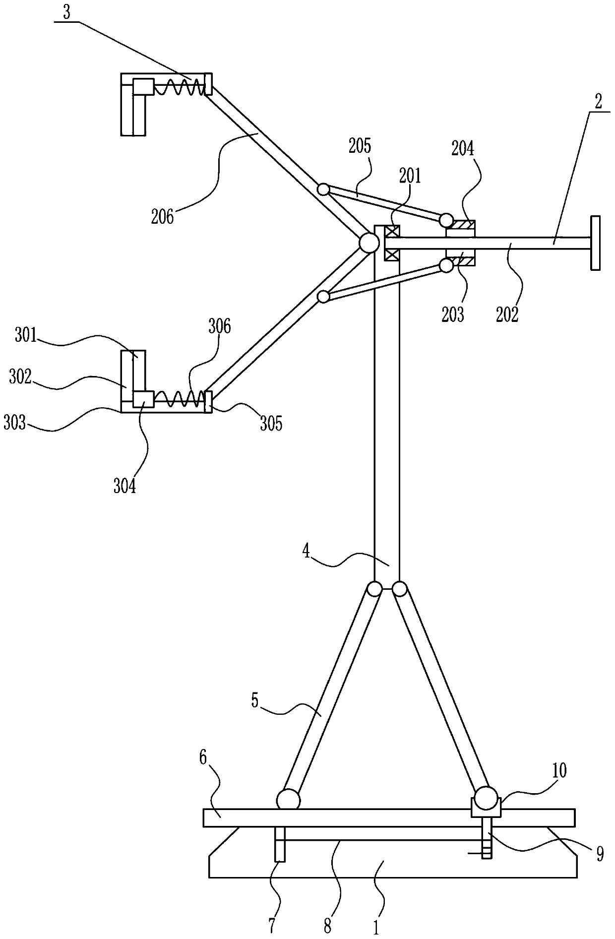
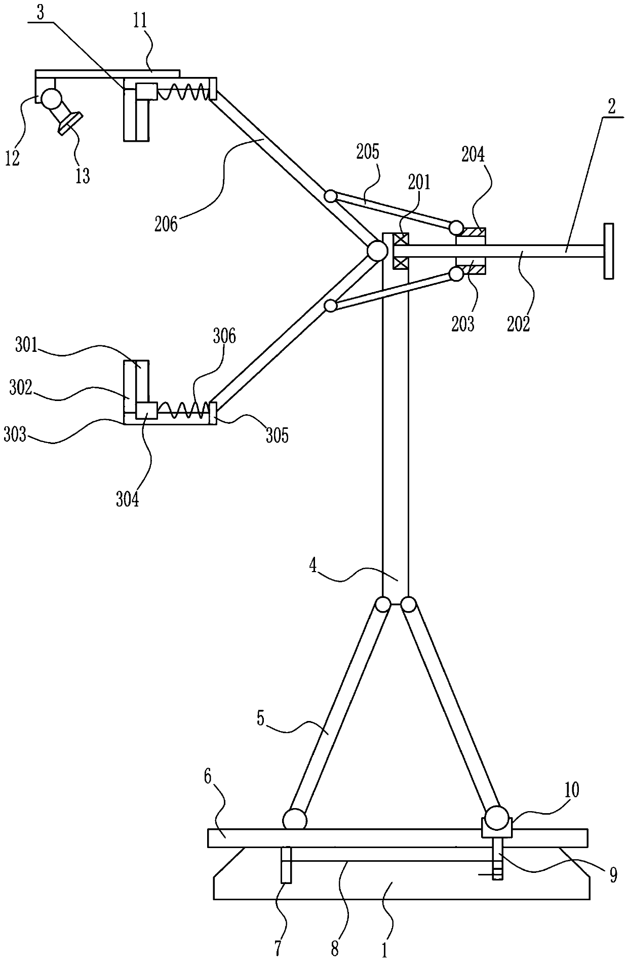
[0027] An ophthalmic eye chart clamping device, such as Figure 1-3 As shown, it includes a base 1, a stretching mechanism 2, a clamping mechanism 3 and a support rod 4. The support rod 4 is connected to the top of the base 1, the stretching mechanism 2 is connected to the upper side of the support rod 4, and the clamping mechanism 2 is connected to the left side of the stretching mechanism 2. Institution 3.
Embodiment 2
[0029] An ophthalmic eye chart clamping device, such as Figure 1-3 As shown, it includes a base 1, a stretching mechanism 2, a clamping mechanism 3 and a support rod 4. The support rod 4 is connected to the top of the base 1, the stretching mechanism 2 is connected to the upper side of the support rod 4, and the clamping mechanism 2 is connected to the left side of the stretching mechanism 2. Institution 3.
[0030] The stretching mechanism 2 includes a bearing seat 201, a first rotating rod 202, a moving block 204, a first connecting rod 205 and a second rotating rod 206, and the upper side of the left wall of the support rod 4 is connected with the second rotating rod 206 in a symmetrical rotation up and down. The right side of the second rotating rod 206 is rotatably connected with the first connecting rod 205, and the right side of the first connecting rod 205 on the upper and lower sides is rotatably connected with the moving block 204, and the middle part of the moving ...
Embodiment 3
[0032] An ophthalmic eye chart clamping device, such as Figure 1-3As shown, it includes a base 1, a stretching mechanism 2, a clamping mechanism 3 and a support rod 4. The support rod 4 is connected to the top of the base 1, the stretching mechanism 2 is connected to the upper side of the support rod 4, and the clamping mechanism 2 is connected to the left side of the stretching mechanism 2. Institution 3.
[0033] The stretching mechanism 2 includes a bearing seat 201, a first rotating rod 202, a moving block 204, a first connecting rod 205 and a second rotating rod 206, and the upper side of the left wall of the support rod 4 is connected with the second rotating rod 206 in a symmetrical rotation up and down. The right side of the second rotating rod 206 is rotatably connected with the first connecting rod 205, and the right side of the first connecting rod 205 on the upper and lower sides is rotatably connected with the moving block 204, and the middle part of the moving b...
PUM
 Abstract
Description
Claims
Application Information
 - R&D
- Intellectual Property
- Life Sciences
- Materials
- Tech Scout
- Unparalleled Data Quality
- Higher Quality Content
- 60% Fewer Hallucinations
Browse by: Latest US Patents, China's latest patents, Technical Efficacy Thesaurus, Application Domain, Technology Topic, Popular Technical Reports.
© 2025 PatSnap. All rights reserved.Legal|Privacy policy|Modern Slavery Act Transparency Statement|Sitemap|About US| Contact US: help@patsnap.com


