
A height angle adjustable fan assembly

A technology for adjusting fans and angles, applied in pump components, mechanical equipment, machines/engines, etc., can solve problems such as the inability to adjust the angle according to needs

Active Publication Date: 2020-12-11
浙江莱恩克风机有限公司
View PDF5 Cites 0 Cited by
  • Summary
  • Abstract
  • Description
  • Claims
  • Application Information

AI Technical Summary

Problems solved by technology

[0002] In the existing axial flow fan assembly, the base of the axial flow fan is generally fixed on the connection plate, the bottom of the connection plate is fixed with outriggers, and the outriggers are fixed at the installation place, and the blowing direction of the axial flow fan is fixed, which cannot be adjusted according to needs. Angle adjustment, so that it cannot meet the needs of different working conditions or different customers

Method used


Image

  • A height angle adjustable fan assembly
  • A height angle adjustable fan assembly
  • A height angle adjustable fan assembly

Examples


Embodiment Construction

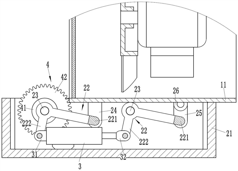
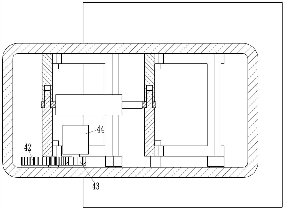
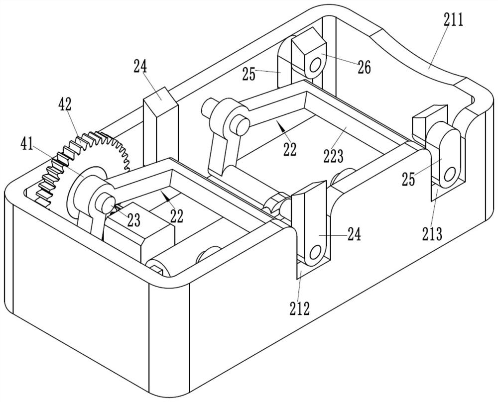
[0017] Examples, see e.g. Figure 1 to Figure 5 As shown, a fan assembly with adjustable height and angle includes a fan and an adjustment seat. The fan includes a fan cylinder 11, a motor is fixed inside the fan cylinder, an impeller is connected to the motor, and a filter screen is provided on the left side of the impeller. The adjustment seat includes a rectangular base 21 with an upper opening. The rectangular base 21 is provided with two T-shaped frame frames 22 arranged left and right. On the inner wall of the rectangular base 21, the end of the long support arm 221 of the T-plate frame 22 on the left side is hinged on the lower end of the fixed support arm 24, and the upper end of the fixed support arm 24 is fixed on the lower end outer wall of the blower tube 11. The end of the long arm 221 of the T-plate type frame 22 is hinged on the lower end of the connecting arm 25, and the upper end of the connecting arm 25 is hinged on the hinged seat 26, and the hinged seat 26 ...


PUM


Abstract

The invention discloses a height-and-angle-adjustable draught fan assembly. The height-and-angle-adjustable draught fan assembly comprises a draught fan and an adjusting seat; the draught fan comprises an air duct; the adjusting seat comprises a rectangular base; two T-shaped plate frames which are located in a left-right direction are arranged in the rectangular base; the bent parts of the T-shaped plate frames are inserted into a supporting shaft in a sleeved manner; the supporting shaft is fixed on the rectangular base; the end of the long support arm of the left T-plate frame is hinged tothe lower end of a fixed supporting arm; the upper end of the fixed supporting arm is fixed to the outer wall of the lower end of the air duct; the end portion of the long support arm of the right T-plate frame is hinged to the lower end of a connecting arm; the upper end of the connecting arm is hinged to a hinge seat; the hinge seat is fixed to the outer wall of the lower end of the air duct; anelectric telescopic cylinder is arranged between the left T-shaped plate frame and the right T-shaped plate frame; and the left T-shaped plate frame is provided with a driving mechanism for driving the T-shaped plate frame to rotate. The position height of the draught fan can be adjusted; the air blowing angle of the draught fan can be adjusted; and the requirements of different working conditions or customers can be met.

Description

technical field [0001] The invention relates to the technical field of fans, in particular to a height-angle-adjustable fan assembly. Background technique [0002] In the existing axial flow fan assembly, the base of the axial flow fan is generally fixed on the connection plate, the bottom of the connection plate is fixed with outriggers, and the outriggers are fixed at the installation place. The blowing direction of the axial flow fan is fixed, which cannot be adjusted according to the needs. Angle adjustment can not meet the needs of different working conditions or different customers. Contents of the invention [0003] The purpose of the present invention is to overcome the deficiencies of the prior art and provide a height-angle adjustable fan assembly, which can adjust the position and height of the fan, and can adjust the blowing angle of the fan to meet different working conditions or customer needs. [0004] The scheme that the present invention solves described ...

Claims


Application Information

Patent Timeline
Patent Type & Authority Patents(China)
IPC IPC(8): F04D25/08F04D27/00F04D29/00
CPCF04D25/08F04D27/00F04D29/002
Inventor 谢浔
Owner 浙江莱恩克风机有限公司
Learn More