Cutting circular saw

A circular saw and saw blade technology, applied in the field of electric tools, can solve the problems of blocking sight, easy shaking, low processing accuracy, etc., and achieve the effect of reducing technical requirements

Active Publication Date: 2018-03-16
POSITEC POWER TOOLS (SUZHOU) CO LTD
View PDF7 Cites 0 Cited by
  • Summary
  • Abstract
  • Description
  • Claims
  • Application Information

AI Technical Summary

Problems solved by technology

However, due to the problem that the shield blocks part of the line of sight and the manual operation is easy to shak

Method used


Image

  • Cutting circular saw
  • Cutting circular saw
  • Cutting circular saw

Examples


Example Embodiment

[0034] Example 1

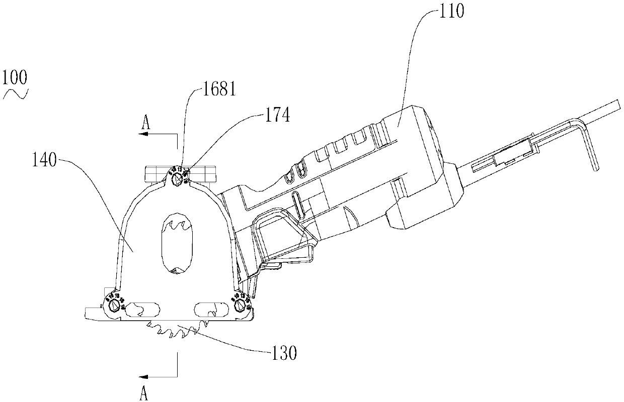
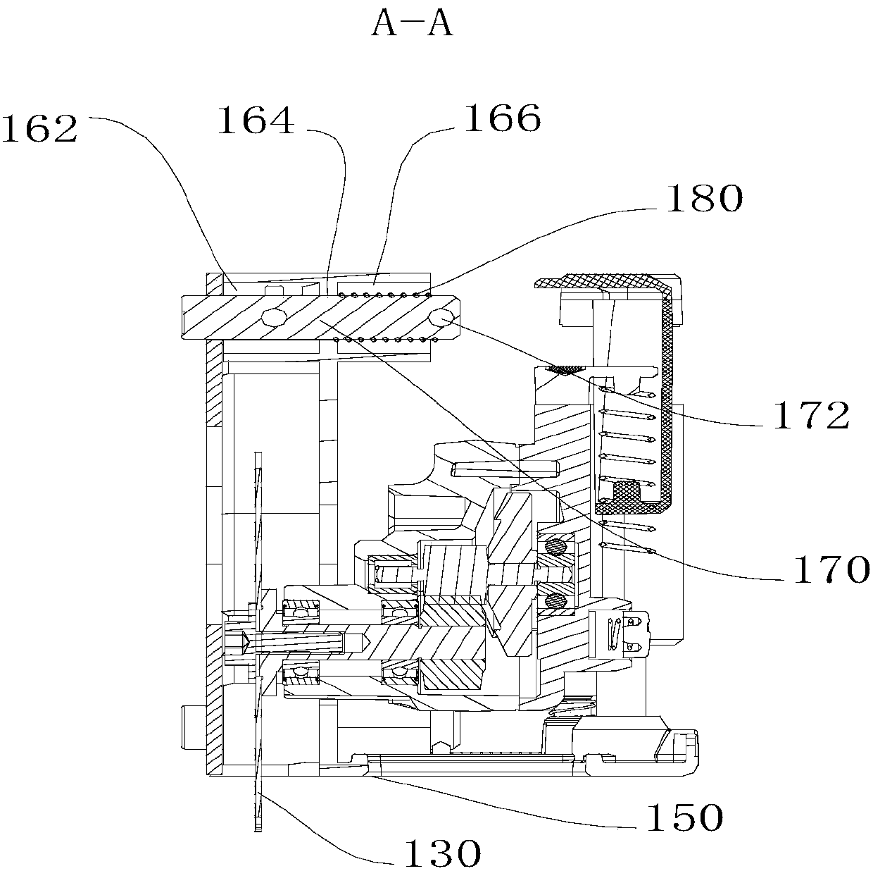
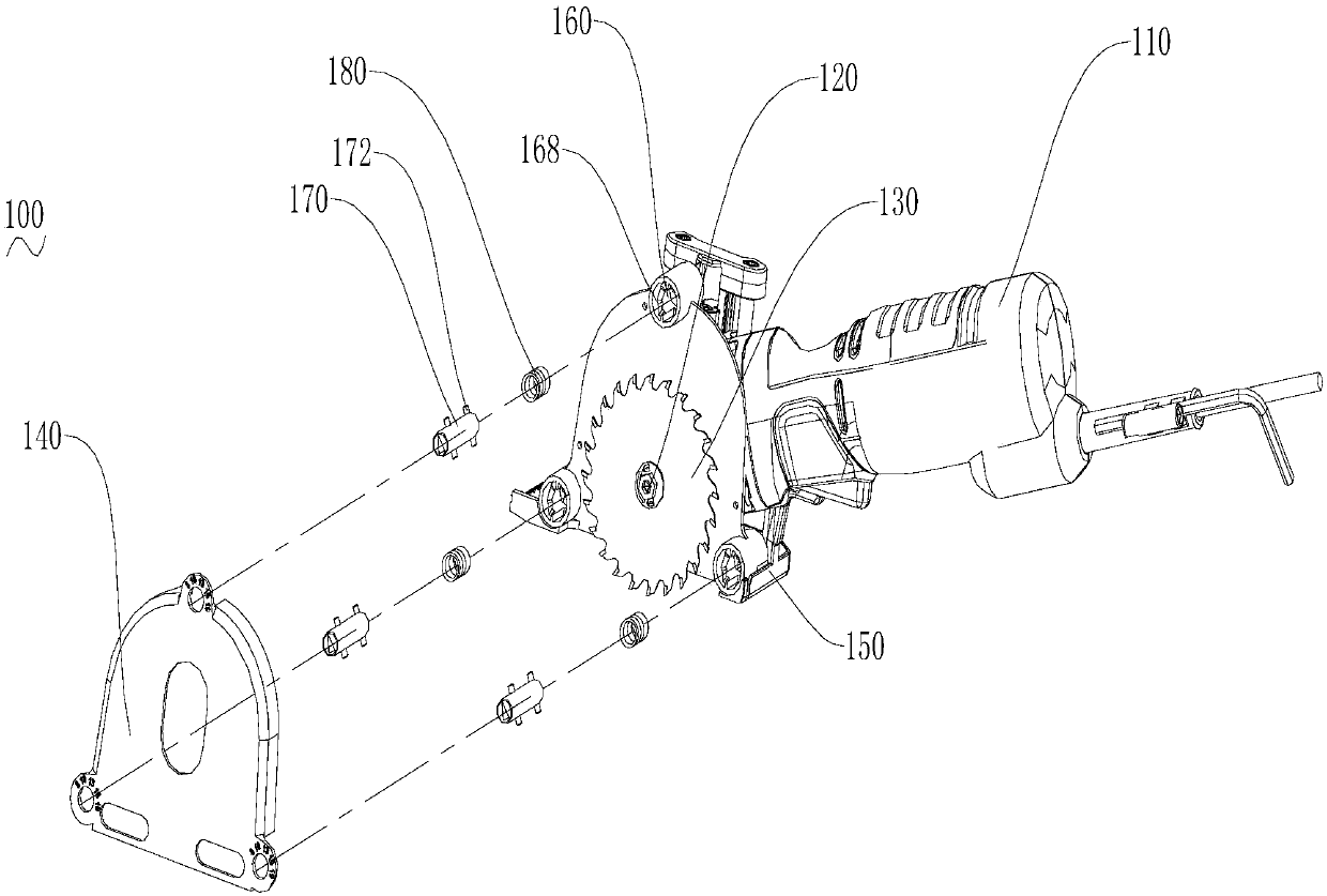
[0035] The cutting circular saw of the present invention includes a casing 110, a motor is installed in the rear casing of the casing 110, a transmission mechanism and an output shaft 120 are installed in the front casing, and a saw blade 130 is installed on the output shaft 120 for To eliminate potential safety hazards, a guard 140 covering the saw blade 130 is also installed on the housing 110. The bottom end of the front part of the housing 110 has a base 150. The base 150 is provided with a through hole for the saw blade 130 to pass through. When cutting, the operator operates the circular saw to expose the saw blade 130 downward from the through hole of the base. The output shaft 120 is driven to rotate through the transmission mechanism, and the saw blade 130 is driven to rotate for cutting.

[0036] The casing 110 is equipped with a pitch adjusting device that can extend parallel to the output shaft 120 toward the outside of the casing and beyond the oute...

Example Embodiment

[0048] Example 2

[0049] Such as Figure 5 As shown, a cutting circular saw includes a casing 110. The casing is provided with an output shaft and a power driving device that drives the output shaft to rotate. A saw blade 130 is installed on the output shaft. The casing is also provided with a cover on the saw blade. On the shield 140; the bottom end of the front of the housing 110 has a base 150, the base 150 is provided with a through hole for the saw blade 130 to pass, when cutting, the operator operates the circular saw to make the saw blade 130 from the through hole of the base The middle is exposed downward, and the motor drives the output shaft to rotate through the transmission mechanism, which drives the saw blade 130 to rotate for cutting.

[0050] The cutting circular saw is equipped with a pitch adjusting device that can extend parallel to the outer side of the output shaft of the casing, extend beyond the outer side of the shield and be positioned. The pitch adjustin...


PUM


Abstract

The invention particularly provides a cutting circular saw which comprises a case, a power driving device, a transmission mechanism and an output shaft. A saw blade is mounted on the output shaft, andthe case is further provided with a shield arranged on the saw blade in a covering mode. A distance adjusting device capable of being in parallel with the output shaft to stretch outwards to exceed the outer side face of the shield by a section of distance and conduct positioning is mounted on the case. When a material close to the wall face needs to be cut, the distance between a to-be-cut lineand the wall face is measured firstly, and the distance is the designated distance. The distance adjusting device is parallel to the output shaft to stretch outwards to exceed the outer side face of the shield by the designated distance, then the outer side face of the distance adjusting device abuts against the wall face to forwards push the circular saw to cut, and thus the needed material can be accurately cut. The situations that a marker line is marked in advance, and whether saw teeth are aligned at the marker line or not is observed by the human eyes are not needed, and meanwhile the technical requirements for operators are also lowered.

Description

technical field [0001] The invention relates to an electric tool, in particular to a cutting circular saw capable of adjusting the cutting position to a required position. Background technique [0002] Circular saw generally comprises casing, and motor, transmission mechanism and output shaft are installed in the casing, and saw blade is installed on this output shaft, also sets up a shield outside saw blade. [0003] In daily work, users often need to remove a small part of a whole workpiece for further processing. The traditional method is to draw a marking line on the workpiece to show the cutting position, and then cut along the marking line. However, due to the problems that the shield blocks a part of the line of sight and the manual operation is easy to shake during cutting, the actual cutting line is easy to deviate from the marking line, and the processing accuracy is low. Contents of the invention [0004] Based on this, it is necessary to provide a cutting circ...

Claims


Application Information

Patent Timeline
IPC IPC(8): B23D45/16B23D47/04
CPCB23D45/16B23D47/04
Inventor 吉绍山陈国军齐献山
Owner POSITEC POWER TOOLS (SUZHOU) CO LTD
Why Eureka
Try Eureka