Traffic light pole washing equipment
A technology for cleaning equipment and traffic lights, applied in cleaning methods and utensils, cleaning methods using tools, cleaning methods using liquids, etc., and can solve problems such as inconvenience in cleaning
- Summary
- Abstract
- Description
- Claims
- Application Information
AI Technical Summary
Problems solved by technology
Method used
Image
Examples
Embodiment 1
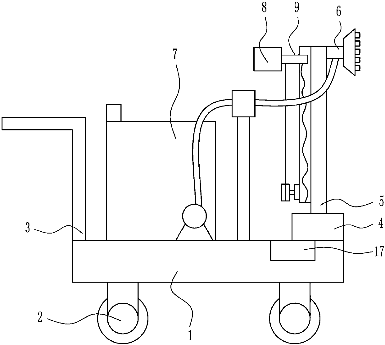
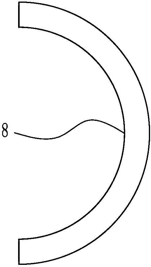
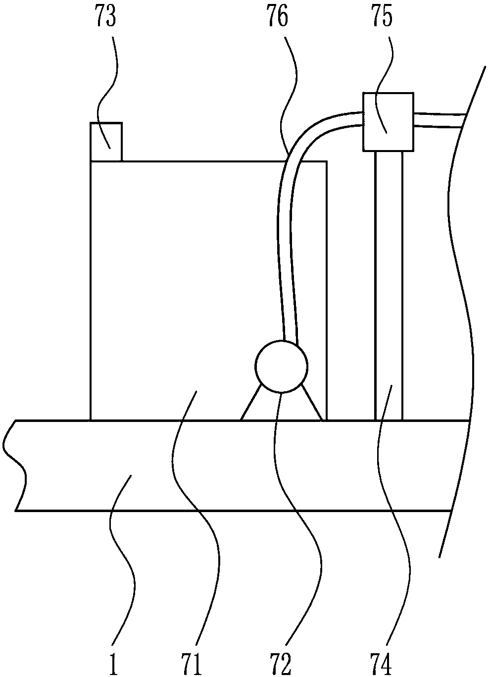
[0030] A traffic light pole cleaning equipment, such as Figure 1-6 As shown, it includes base plate 1, wheel 2, push rod 3, bearing seat 4, first rotating shaft 5, nozzle 6, water delivery device 7, arc wiper 8, lifting device 9 and storage battery 17, and the bottom of base plate 1 is symmetrically arranged. There are wheels 2, a push rod 3 is provided on the left side of the top of the base plate 1, a water delivery device 7 is provided on the top of the base plate 1 on the right side of the push rod 3, a bearing seat 4 is provided on the right side of the top of the base plate 1, and a first rotating shaft is arranged in the bearing seat 4 5. There is a nozzle 6 on the upper right side of the first rotating shaft 5, the bottom of the nozzle 6 is connected with the water delivery device 7, the lifting device 9 is arranged on the left side of the first rotating shaft 5, and the arc-shaped wiper 8 is arranged on the left side of the lifting device 9, and the bottom plate 1 Th...
Embodiment 2
[0032] A traffic light pole cleaning equipment, such as Figure 1-6 As shown, it includes base plate 1, wheel 2, push rod 3, bearing seat 4, first rotating shaft 5, nozzle 6, water delivery device 7, arc wiper 8, lifting device 9 and storage battery 17, and base plate 1 is symmetrically arranged left and right. There are wheels 2, a push rod 3 is provided on the left side of the top of the base plate 1, a water delivery device 7 is provided on the top of the base plate 1 on the right side of the push rod 3, a bearing seat 4 is provided on the right side of the top of the base plate 1, and a first rotating shaft is arranged in the bearing seat 4 5. There is a nozzle 6 on the upper right side of the first rotating shaft 5, the bottom of the nozzle 6 is connected with the water delivery device 7, the lifting device 9 is arranged on the left side of the first rotating shaft 5, and the arc-shaped wiper 8 is arranged on the left side of the lifting device 9, and the bottom plate 1 T...
Embodiment 3
[0035] A traffic light pole cleaning equipment, such as Figure 1-6 As shown, it includes base plate 1, wheel 2, push rod 3, bearing seat 4, first rotating shaft 5, nozzle 6, water delivery device 7, arc wiper 8, lifting device 9 and storage battery 17, and the bottom of base plate 1 is symmetrically arranged. There are wheels 2, a push rod 3 is provided on the left side of the top of the base plate 1, a water delivery device 7 is provided on the top of the base plate 1 on the right side of the push rod 3, a bearing seat 4 is provided on the right side of the top of the base plate 1, and a first rotating shaft is arranged in the bearing seat 4 5. There is a nozzle 6 on the upper right side of the first rotating shaft 5, the bottom of the nozzle 6 is connected with the water delivery device 7, the lifting device 9 is arranged on the left side of the first rotating shaft 5, and the arc-shaped wiper 8 is arranged on the left side of the lifting device 9, and the bottom plate 1 Th...
PUM
 Abstract
Description
Claims
Application Information
 - R&D
- Intellectual Property
- Life Sciences
- Materials
- Tech Scout
- Unparalleled Data Quality
- Higher Quality Content
- 60% Fewer Hallucinations
Browse by: Latest US Patents, China's latest patents, Technical Efficacy Thesaurus, Application Domain, Technology Topic, Popular Technical Reports.
© 2025 PatSnap. All rights reserved.Legal|Privacy policy|Modern Slavery Act Transparency Statement|Sitemap|About US| Contact US: help@patsnap.com


