
A microwave induction led bulb

An LED bulb and microwave induction technology, applied in the field of lighting, can solve the problems of difficult signal transmission, instability, inconvenient switching state, etc., and achieve the effects of easy mechanized production, high production efficiency, and stable signal transmission and reception.

Active Publication Date: 2020-02-11
FOSHAN ELECTRICAL & LIGHTING
View PDF7 Cites 0 Cited by
  • Summary
  • Abstract
  • Description
  • Claims
  • Application Information

AI Technical Summary

Problems solved by technology

[0002] LED light bulbs are widely used due to their unique advantages. At present, the commonly used LED light bulbs are controlled by switches to control the switch status of LED bulbs. However, for some public places, it is extremely inconvenient to control the switch status by switches. induction light bulb
[0003] At present, the wireless control modules of microwave induction bulbs on the market are all installed at the bottom of the lamp board. The lamp board is usually supported by an aluminum substrate. When the wireless control module transmits and receives signals, it needs to penetrate the aluminum substrate to realize the signal transmission. The difficulty of signal transmission It is large and unstable, which brings a lot of inconvenience to the use of the light bulb. Therefore, it is necessary to propose a LED light bulb with stable signal transmission to solve the above problems

Method used


Image

  • A microwave induction led bulb
  • A microwave induction led bulb
  • A microwave induction led bulb

Examples


Embodiment Construction

[0026] In order to enable those skilled in the art to better understand the technical solutions of the present invention, the present invention will be further described in detail below in conjunction with the accompanying drawings and preferred embodiments.

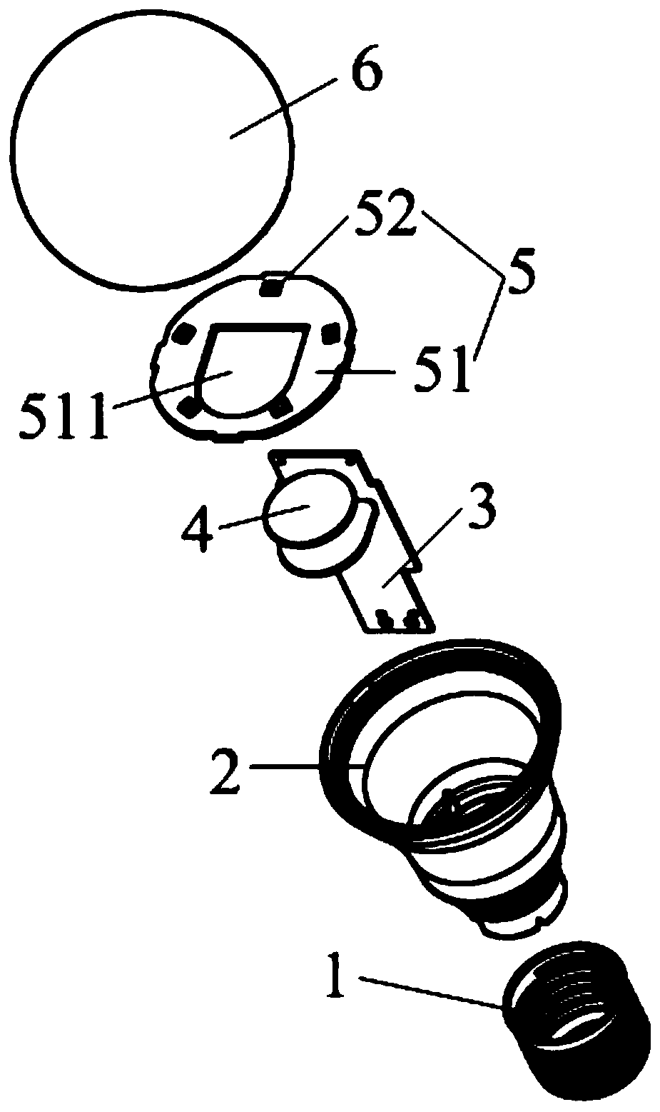
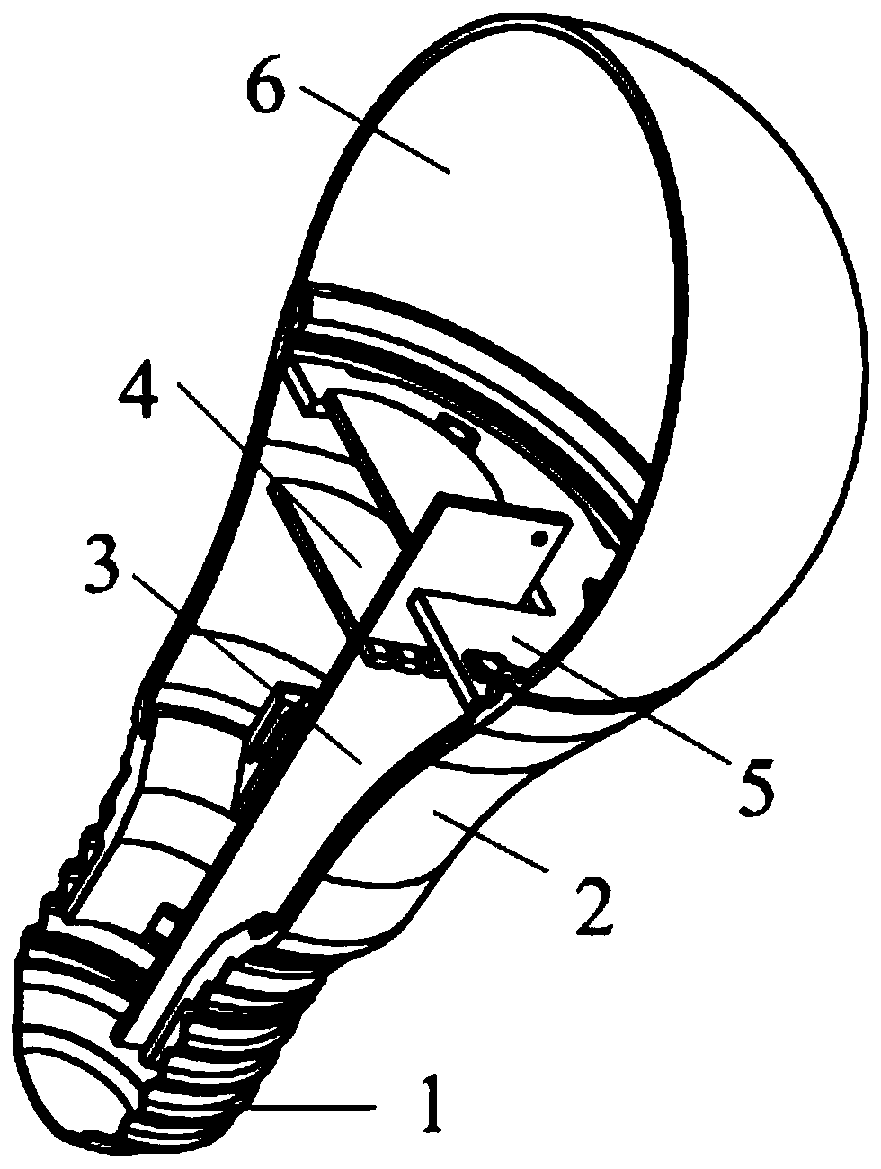
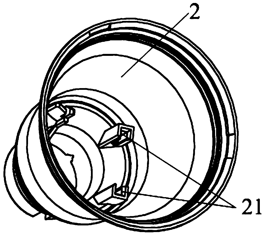
[0027] Such as Figure 1-5 As shown, a microwave induction LED light bulb includes a lamp base 1, a housing 2 connected to the lamp base 1, a driving power board 3 located inside the housing 2, and a wireless control module connected to the driving power board 3 4. The LED light board 5 located on the casing 2 and the lampshade 6 connected to the casing 2;

[0028] The LED light board 5 includes a base plate 51 and a lamp bead 52 located on the base plate 51, the base plate 51 is provided with a mounting hole 511, and the shape and size of the mounting hole 511 is the same as that of the wireless control module 4 and size match;

[0029] The driving power board 3 includes a fixing hole 31 and an electrode area 32 locat...


PUM


Abstract

The invention relates to a microwave induction LED lamp bulb. The microwave induction LED lamp bulb comprises a lamp cap, a shell connected with the lamp cap, a driving power board located inside theshell, a wireless control module connected with the driving power board, an LED lamp board located on the shell and a lampshade connected with the shell; the LED lamp board comprises a base plate andlamp beads located on the base plate, an installing hole is formed in the base plate, and the shape and size of the installing hole are matched with the shape and size of the wireless control module;the driving power board comprises a fixed hole and electrode zones located around the fixed hole; and the wireless control module comprises a pin and conducting layers, and the conducting layers are matched with the electrode zones in number, size and position. The microwave induction LED lamp bulb is convenient and quick to install, and mechanized production is facilitated; and compared with a traditional manner needing manual welding of the driving power board and the wireless control module, the production efficiency is high, and the production cost is saved.

Description

technical field [0001] The invention relates to the technical field of lighting, in particular to a microwave induction LED light bulb. Background technique [0002] LED light bulbs are widely used due to their unique advantages. At present, the commonly used LED light bulbs are controlled by switches to control the switch status of LED bulbs. However, for some public places, it is extremely inconvenient to control the switch status by switches. Inductive bulbs. [0003] At present, the wireless control modules of microwave induction bulbs on the market are all installed at the bottom of the lamp board. The lamp board is usually supported by an aluminum substrate. When the wireless control module transmits and receives signals, it needs to penetrate the aluminum substrate to realize the signal transmission. The difficulty of signal transmission It is large and unstable, which brings a lot of inconvenience to the use of the light bulb. Therefore, it is necessary to propose a...

Claims


Application Information

Patent Timeline
Patent Type & Authority Patents(China)
IPC IPC(8): F21K9/232F21K9/238F21V23/00F21V23/06F21Y115/10
CPCF21K9/232F21K9/238F21V23/005F21V23/06F21Y2115/10
Inventor 谢姜魏彬朱奕光
Owner FOSHAN ELECTRICAL & LIGHTING
Learn More