Automatic power supply inserting-connecting apparatus

A power supply plug-in and automatic technology, which is applied to the parts of the connecting device, the device to prevent contact with live contacts, the coupling device, etc., can solve the electric shock accidents of young children, the life danger of young children, and the power supply tank without protective devices, etc. problems, to achieve the effect of reducing electric shock accidents and increasing safety and stability

Inactive Publication Date: 2018-03-27
成都中创空间科技有限公司
View PDF0 Cites 16 Cited by
  • Summary
  • Abstract
  • Description
  • Claims
  • Application Information

AI Technical Summary

Problems solved by technology

[0002] At present, the use of electrical equipment needs to be inserted into the power supply tank before it can be used. However, the existing household sockets are basically installed in the wall, and the power supply tank on the socket is directly connected to the mains. The plug of the device can be plugged directly into the power supply slot to be powered on. Although this plugging method is very convenient to operate, the power supply slot will always be powered on, and the power supply slot is not equipped with a protective device that can be covered. If there are young children at home Inserting fingers or metal rods into the power supply tank under the supervision of people will cause electric shock accidents for young children, and in severe cases, it will cause life-threatening danger to young children. There is a big safety hazard in the plugging method, and the power supply of the power supply slot is unstable

Method used


Image

  • Automatic power supply inserting-connecting apparatus
  • Automatic power supply inserting-connecting apparatus
  • Automatic power supply inserting-connecting apparatus

Examples


Embodiment Construction

[0021] The preferred embodiments of the present invention will be described in detail below in conjunction with the accompanying drawings, so that the advantages and features of the present invention can be more easily understood by those skilled in the art, so as to define the protection scope of the present invention more clearly.

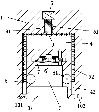
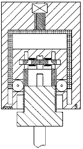
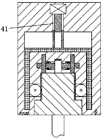
[0022] refer to Figure 1-6 The shown automatic power supply plug-in device includes a power supply part 1 and a plug part 2 inserted into the power supply part 1 for mating connection. The power supply part 1 is provided with a card slot 31 opening forward. The rear end wall of the card slot 31 is provided with a slot 3 communicating with the card slot 31, and the rear end wall of the slot 3 is provided with a power supply slot 6 communicated with the slot 3, and the power supply slot 6 The power supply parts 1 on the left and right sides are symmetrically provided with operation slots 7 communicating with the slots 3, and the power supply parts...


PUM


Abstract

The invention discloses an automatic power supply inserting-connecting apparatus. The automatic power supply inserting-connecting apparatus comprises a power supply part and a plug part inserted intothe power supply part to be matched and connected therewith; a clamping groove with a forward opening is formed in the power supply part; a slot connected with the clamping groove is formed in the back end wall of the clamping groove; a power supply groove connected with the slot is formed in the back end wall of the slot; operating grooves connected with the slot are symmetrically formed in the power supply part on the left and right sides of the power supply groove; sealing apparatuses for sealing the power supply groove are also symmetrically arranged in the power supply part on the left and right sides of the power supply groove; a sliding groove is also formed in the power supply part; and a sleeve groove which extends backwardly is also formed in the middle position of the back end wall of the sliding groove. The automatic power supply inserting-connecting apparatus is simple in the overall structure, safe and stable in power supply, safe and reliable in overall operation, capable of effectively lowering electric shock accidents in the existing life and ensuring child life security in a family, and suitable for popularization and use.

Description

technical field [0001] The invention relates to the field of power supply, in particular to an automatic power supply plug-in device. Background technique [0002] At present, the use of electrical equipment needs to be plugged into the power supply tank before it can be used. However, the existing household sockets are basically installed in the wall, and the power supply tank on the socket is directly connected to the mains. The plug of the device can be plugged directly into the power supply slot to be powered on. Although this plugging method is very convenient to operate, the power supply slot will always be powered on, and the power supply slot is not equipped with a protective device that can be covered. If there are young children at home Inserting fingers or metal rods into the power supply tank under the supervision of people will cause electric shock accidents for young children, and in severe cases, it will cause life-threatening danger to young children. There ...

Claims


Application Information

Patent Timeline
Patent Type & Authority Applications(China)
IPC IPC(8): H01R13/44H01R13/629H01R13/703
CPCH01R13/44H01R13/629H01R13/62933H01R13/7031
Inventor 胡龙
Owner 成都中创空间科技有限公司
Why Eureka
Try Eureka