Imaging device and method

An imaging device and data processing unit technology, applied in optical elements, optics, instruments, etc., can solve the problems of low output light energy density, long imaging time, weak return light signal, etc., so as to reduce calculation time and improve signal-to-noise ratio. , the effect of energy concentration

Pending Publication Date: 2018-03-30
苏州蛟视智能科技有限公司
View PDF4 Cites 6 Cited by
  • Summary
  • Abstract
  • Description
  • Claims
  • Application Information

AI Technical Summary

Problems solved by technology

[0007] The present invention provides an imaging device and method to solve the problems of weak return light signal, low signal-to-noise ratio, long imaging time and low output light energy density in the prior art under bad weather conditions or in water

Method used


Image

  • Imaging device and method
  • Imaging device and method
  • Imaging device and method

Examples


Embodiment 1

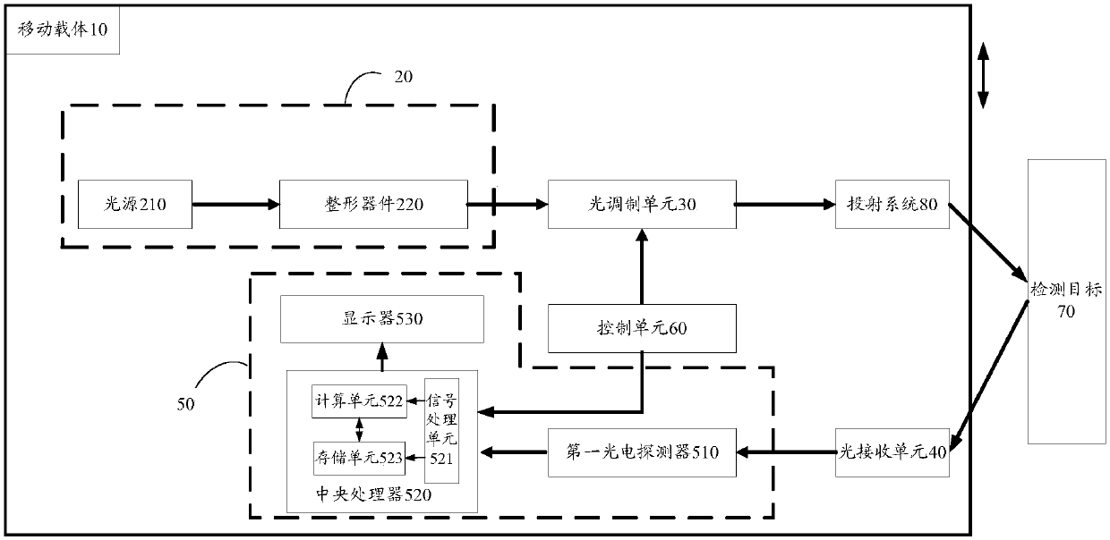
[0062] Such as figure 1 As shown, the present invention provides an imaging device, including a mobile carrier 10, a structured light source 20 located on the mobile carrier 10, a light modulation unit 30, a light receiving unit 40, a data processing unit 50, and a light modulating The control unit 60 connected to the unit 30 and the data processing unit 50, the structured light source 20 generates a structured light beam and passes through the light modulation unit 30 to generate a spot of required energy distribution and projects it onto the detection target 70, the detection target 70 The reflected light is received by the light receiving unit 40 and transmitted to the data processing unit 50, and the data processing unit 50 synchronously receives the data of the control unit 60 and the light receiving unit 40 and performs a correlation operation to obtain an imaging result. The light modulation unit 30 includes several reflectors 310 arranged to form a micromirror reflecti...

Embodiment 2

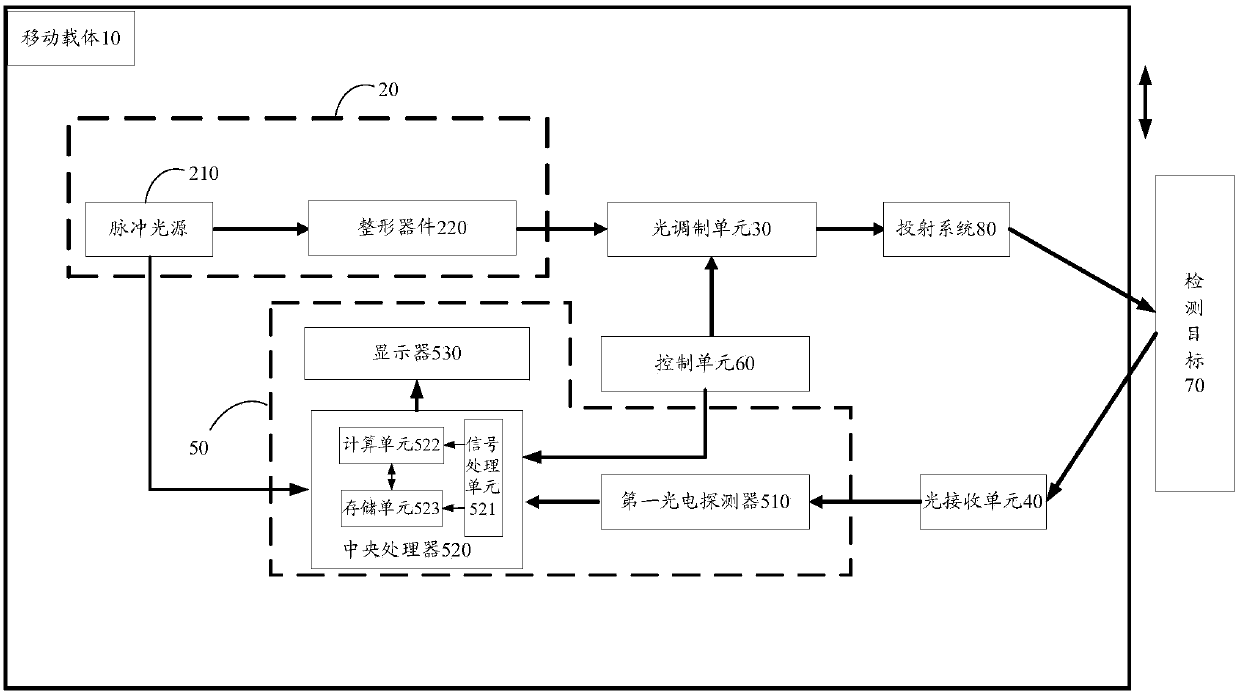
[0076] Such as image 3 As shown, the difference from Embodiment 1 is that in this embodiment, the light source 210 is a pulsed light source, and the pulsed light source is connected to the data processing unit 50, and transmits the electrical synchronization signal for controlling light emission to the data processing unit 50. Unit 50, marking the light emitting time of each pulse. The data processing unit 50 includes a first photodetector 510, a central processing unit 520 and a display 530 connected in sequence, the first photodetector 510 adopts a single-point light intensity detector and is connected with the light receiving unit 40, The central processing unit 520 is connected with the control unit 60 and the pulse light source. Specifically, when a continuous light source is used, the echo signal does not contain distance information, and can only image the range irradiated by the modulated light spot within the field of view. When the pulse light source is used, the ...

Embodiment 3

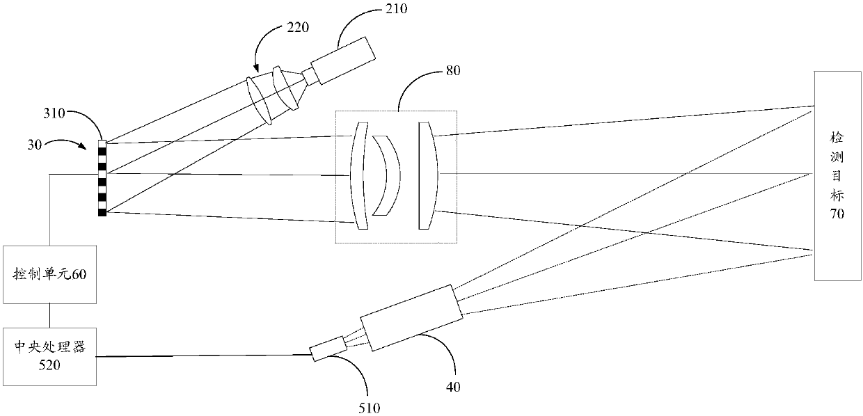
[0084] Such as Figure 4 As shown, the difference from Embodiment 1-2 is that in this embodiment, the light source 210 is a pulsed light source, and the light modulation unit 30 is further provided with a spectroscopic device 910 and a light source connected to the spectroscopic device 910 along the optical path. The second photodetector 920, the second photodetector 920 is connected to the data processing unit 50, marks the light pulse signal received by the second photodetector 920 as the light emitting time of each pulse. exist Figure 4 Among them, the spectroscopic device 910 is located behind the projection system 80, and of course it can also be located between the light modulation unit 30 and the projection system 80. Compared with Embodiment 2, it can better avoid light delay, so as to ensure that the central processing unit 520 can better Signals from the pulsed light source and the detection target 70 are received synchronously. Preferably, the data processing uni...


PUM


Abstract

The invention discloses an imaging device and a method. The imaging device is characterized in that the device comprises a mobile carrier, a structured light source, an optical modulation unit, an optical receiving unit, a data processing unit, and a control unit, wherein the structured light source, the optical modulation unit, the optical receiving unit and the data processing unit are located on the mobile carrier, and the control unit is connected with the optical modulation unit and the data processing unit; the structured light source generates structured light beams to pass through theoptical modulation unit and generate a light spot with a desired energy distribution and be projected onto a detection target; reflected light of the detection target is received and transmitted to the data processing unit through the optical receiving unit; the data processing unit synchronously receives data from the control unit and the optical receiving unit and then conducts association operation to obtain an imaging result; the optical modulation unit comprises a plurality of reflectors and a micromirror reflector array; The micromirror reflector array is formed by the arrangement of themultiple reflectors and is consistent with the shape of the light spot of the structured light beams. The imaging device and method have the advantages of realizing light beam dimensionality reduction or simplification modulation, improving light beam energy density and signal-to-noise ratio of an echo signal, and enhancing correlation operation speed, imaging distance and quality through structured light treatment.

Description

technical field [0001] The invention relates to the field of target detection, identification and imaging, in particular to an imaging device and method. Background technique [0002] Correlated imaging, also known as ghost imaging, is a quantum or classical correlation characteristic based on light field fluctuations. Through the intensity correlation operation between the reference light field and the target detection light field, the non-definite A new imaging technology that obtains target image information locally. However, traditional correlative imaging has many sampling times, long imaging time, and complex system structure, and is not suitable for imaging in such a complex and changeable environment as water bodies. Compressive Sensing technology is a new signal sampling technology that has emerged in recent years. Different from the traditional Nyquist sampling theorem, this technology synchronizes the signal compression process with the sampling process, that is,...

Claims


Application Information

Patent Timeline
Patent Type & Authority Applications(China)
IPC IPC(8): G02B27/09
CPCG02B27/0916G02B27/0977
Inventor 黄帆韩捷飞初宁蔡栋龙涛邹诚
Owner 苏州蛟视智能科技有限公司
Why Eureka
Try Eureka