Eureka AIR delivers breakthrough ideas for toughest innovation challenges, trusted by R&D personnel around the world.

Dustproof and heat radiation electric power cabinet having fire extinguishing function

A power cabinet and dust-proof technology, which is applied in the direction of electrical components, fire rescue, substation/distribution device shell, etc., can solve the problems of increasing fire, uncontrolled fire, high temperature inside the cabinet, and prevent dust from entering, The effect of preventing the spread of fire and preventing the expansion of fire

Inactive Publication Date: 2018-03-30
HUNAN XIANGXUN ENTERPRISE MANAGEMENT CO LTD
View PDF5 Cites 46 Cited by
  • Summary
  • Abstract
  • Description
  • Claims
  • Application Information

AI Technical Summary

Problems solved by technology

[0003] When the electronic components inside the power cabinet are working, a lot of heat will be generated. Ordinary power cabinets only dissipate heat through opening heat dissipation windows. , the existing power cabinet lacks corresponding safety protection measures. Once a fire occurs in the power cabinet, the electronic components are easily burned, resulting in leakage, increasing the fire, and the fire cannot be controlled. It is easy to spread, which will not only cause huge property losses losses and threaten the personal safety of residents

Method used


Image

  • Dustproof and heat radiation electric power cabinet having fire extinguishing function
  • Dustproof and heat radiation electric power cabinet having fire extinguishing function
  • Dustproof and heat radiation electric power cabinet having fire extinguishing function

Examples


Embodiment Construction

[0019] The following will clearly and completely describe the technical solutions in the embodiments of the present invention with reference to the accompanying drawings in the embodiments of the present invention. Obviously, the described embodiments are only some, not all, embodiments of the present invention. Based on the embodiments of the present invention, all other embodiments obtained by persons of ordinary skill in the art without making creative efforts belong to the protection scope of the present invention.

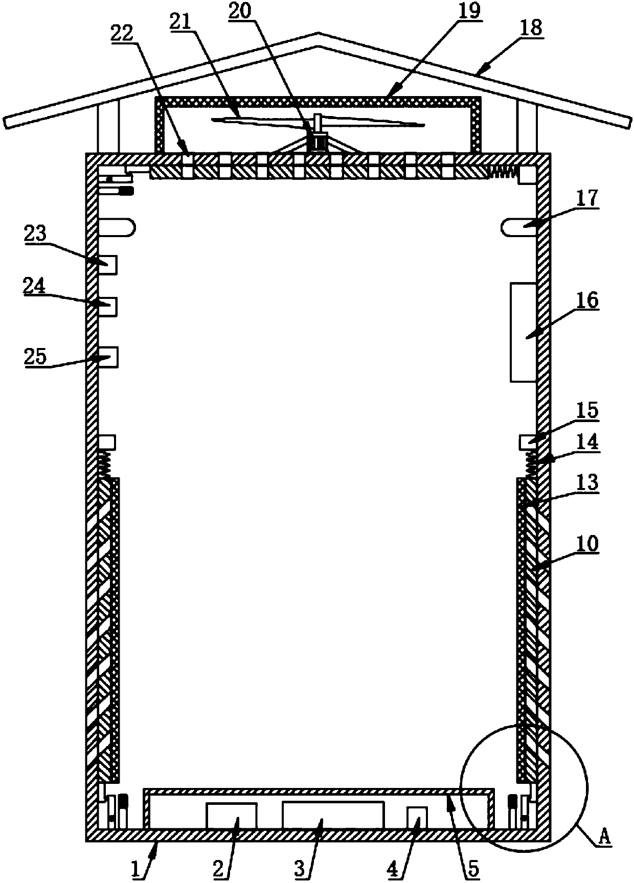
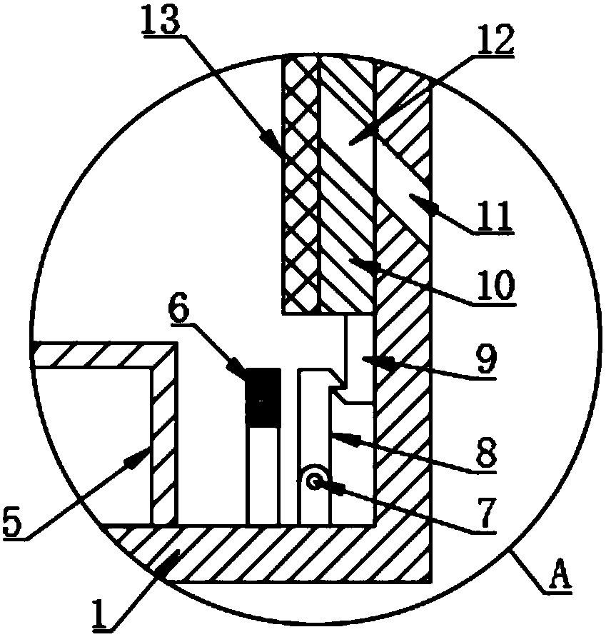
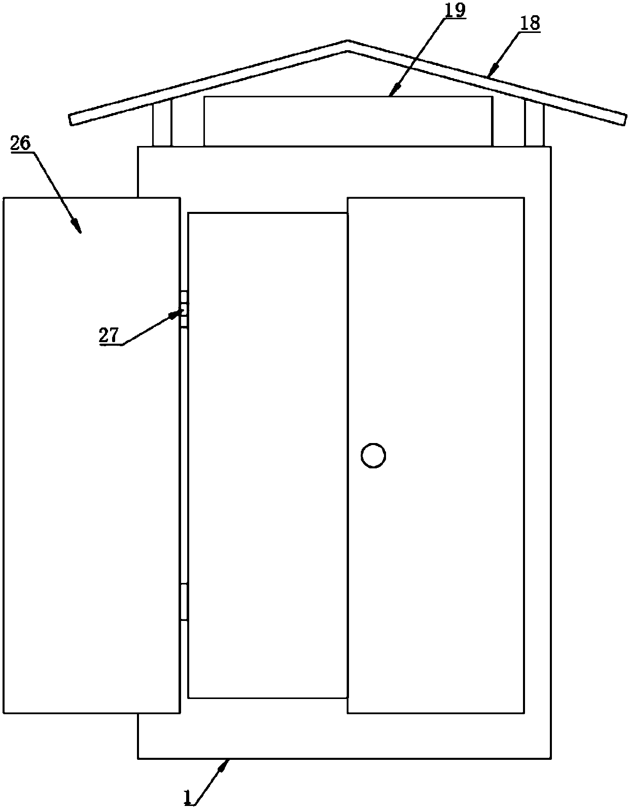
[0020] see Figure 1~4 , in an embodiment of the present invention, a dust-proof and heat-dissipating power cabinet with a fire-extinguishing function includes a power cabinet 1, and a plurality of air inlet holes 11 are uniformly arranged at the bottom of the left and right side walls of the power cabinet 1, and the air inlet holes 11 are directed from the inside to the outside. If it is set at a downward slope, it is difficult for dust to enter into 01 throu...


PUM


Abstract

The invention discloses a dustproof and heat radiation electric power cabinet having a fire extinguishing function. The dustproof and heat radiation electric power cabinet comprises an electric powercabinet. The bottom parts of the left and right side walls of the electric power cabinet are evenly provided with multiple air inlet holes. The middle position of the top wall of the electric power cabinet is evenly provided with multiple air outlet holes. The left and right side walls and the top wall of the electric power cabinet are slidably connected with ventilating plates through slide rails, and the ventilating plates are provided with ventilating holes. The left and right side walls and the top wall of the electric power cabinet are fixedly provided with fixing blocks which are connected with one end of the ventilating plates through springs. The other end of each ventilating plate is fixedly connected with a second buckle. First buckles buckled with the second buckles are hinged on the bottom part and the side walls of the electric power cabinet through supports. The material of the first buckles is iron. Electromagnets matched with the first buckles are fixedly connected on the bottom part and the side walls of the electric power cabinet. Electrification is performed through the electromagnets so that the buckles are enabled to be released, and the ventilating plates slide to seal the air inlet holes and the air outlet holes to isolate oxygen and spreading of the fire can be prevented, the fire can be quickly extinguished and the loss can be reduced.

Description

technical field [0001] The invention relates to the technical field of power facilities, in particular to a dust-proof and heat-dissipating power cabinet with a fire extinguishing function. Background technique [0002] The number of electrical appliances in life is increasing, and a lot of manual labor is replaced by electronic equipment. In order to ensure the stability of power, power cabinets are often used to protect the components of power equipment. Power cabinets are a commonly used power infrastructure. [0003] When the electronic components inside the power cabinet are working, a lot of heat will be generated. Ordinary power cabinets only dissipate heat through opening heat dissipation windows. , the existing power cabinet lacks corresponding safety protection measures. Once a fire occurs in the power cabinet, the electronic components are easily burned, resulting in leakage, increasing the fire, and the fire cannot be controlled. It is easy to spread, which will ...

Claims


Application Information

Patent Timeline
IPC IPC(8): H02B1/56H02B1/28A62C3/16A62C37/40
CPCH02B1/565A62C3/16A62C37/40H02B1/28
Inventor 何辉
Owner HUNAN XIANGXUN ENTERPRISE MANAGEMENT CO LTD
Why Eureka
Eureka Blog
Learn More