High speed loading device for gantry polishing machine
What is Al technical title?
Al technical title is built by PatSnap Al team. It summarizes the technical point description of the patent document.
A polishing machine, gantry-type technology, applied in grinding/polishing safety devices, surface polishing machine tools, grinding drive devices, etc. Effects of stability and security
Active Publication Date: 2020-01-24
HUNAN YUJING MACHINE
View PDF14 Cites 0 Cited by
Summary
Abstract
Description
Claims
Application Information
AI Technical Summary
This helps you quickly interpret patents by identifying the three key elements:
Problems solved by technology
Method used
Benefits of technology
Problems solved by technology
[0002] At present, the upper plate motor of the existing polishing machine is placed in the box, and the dial is driven by the reducer and gear transmission to drive the upper plate to rotate. The upper plate has poor rotation stability, poor precision, high noise, and slow rotation speed. The disk is raised and lowered by the cylinder without guide device, the pressure is small and unstable, and it is difficult to meet the requirements of high precision, high speed and high pressure in the market development
Method used
Image
Click on the blue label to locate the original text in one second.
Reading with bidirectional positioning of images and text.
Examples
Embodiment
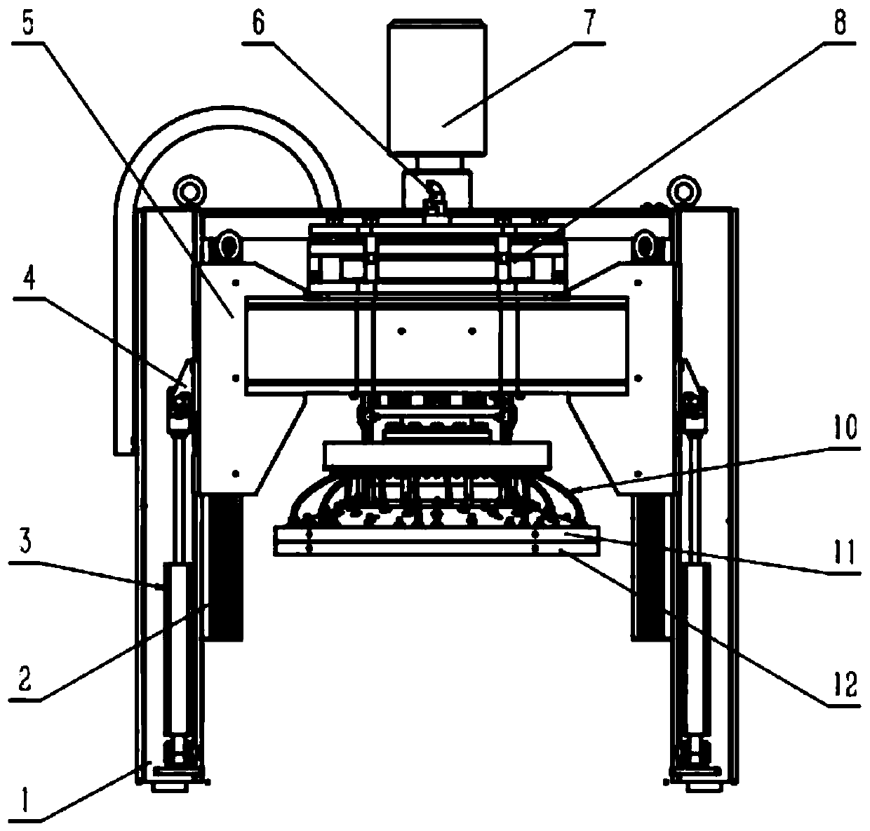
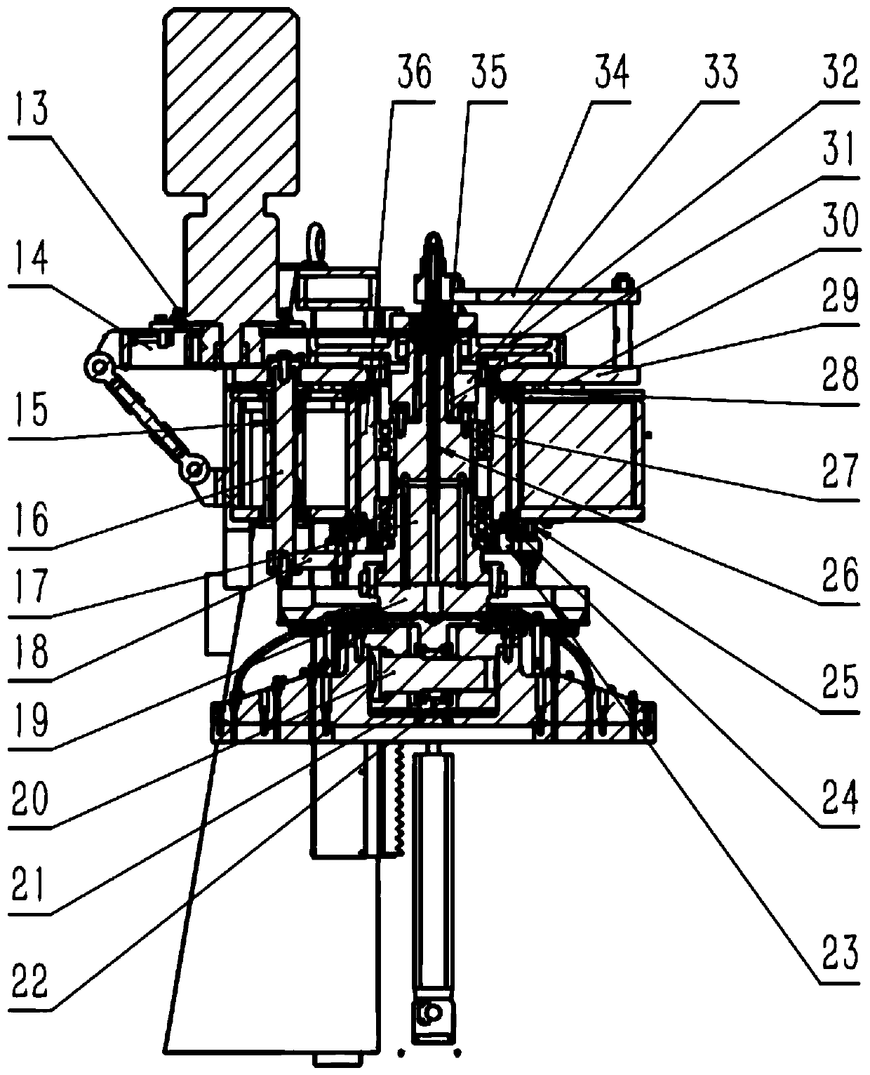
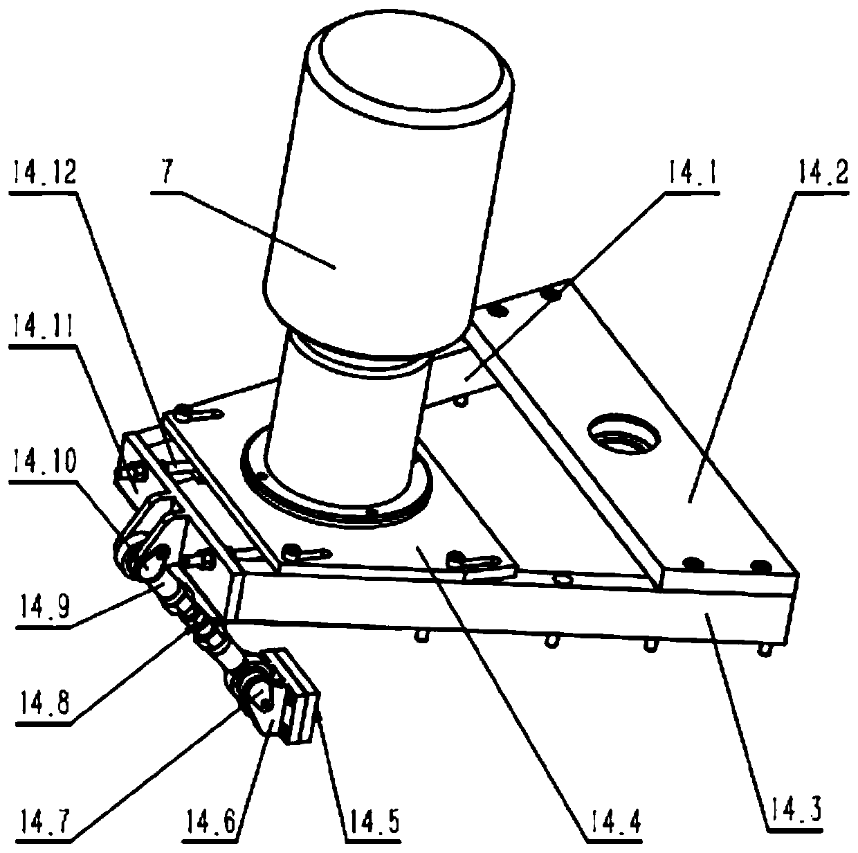
[0020] refer to figure 1 , figure 2 and image 3 , this embodiment includes gantry 1, linear slide rail 2, oil cylinder 3, hinge seat I4, sliding seat 5, rotary joint 6, motor 7, timing belt 8, hose 10, upper plate gland 11, upper polishing plate 12 , small synchronous pulley 13, motor installation assembly 14, guide sleeve 15, guide rod 16, upper main shaft 17, connecting plate 18, lower main shaft 19, pin shaft I20, joint bearing 21, gland 22, lower support plate 23, lower Damping ring 24, rubber damping pad 25, cooling pipe 26, bearing 27, upper damping ring 28, upper support plate 29, damping airbag 30, expansion sleeve 31, large synchronous pulley 32, shaft coupling 33, Counterweight plate 34, self-aligning bearing 35 and bearing seat 36;
[0021] The sliding seat 5 is connected with the gantry 1 through two left and right linear slide rails 2, the upper end of the oil cylinder 3 is connected with the sliding seat 5 through the hinge seat I4, and the sliding seat 5 is...
PUM
Abstract
A high rotating speed upper plate device for a gantry type polishing machine comprises a gantry frame, a linear sliding rail, an oil cylinder, a sliding seat, a rotating joint, a motor, a synchronizing belt, an upper plate pressing cover, an upper polishing disk, a small synchronous pulley, a motor installation assembly, a guiding sleeve, a guide bar, an upper main shaft, a lower main shaft, a joint bearing, a pressing cover, a lower supporting plate, a shock absorption pad, a cooling pipe, an upper supporting plate, a shock absorption airbag, a large synchronous pulley, a coupling, a balanceweight plate, and a bearing seat. The high rotating speed upper plate device has the characteristics that stability of an upper plate is higher, the upper plate rotating speed is higher, and added pressure is greater; and the requirements for the high rotating speed and high pressurization of the market development can be met.
Description
technical field [0001] The invention relates to a high-rotational plate loading device for a gantry type polishing machine. Background technique [0002] At present, the upper plate motor of the existing polishing machine is placed in the box, and the dial is driven by the reducer and gear transmission to drive the upper plate to rotate. The upper plate has poor rotation stability, poor precision, high noise, and slow rotation speed. The disk is raised and lowered by the cylinder without guide device, the pressure is small and unstable, and it is difficult to meet the requirements of high precision, high speed and high pressure in market development. Contents of the invention [0003] The technical problem to be solved by the present invention is to provide a high-speed plate-loading device for a gantry-type polishing machine that does not use a reducer, does not use a gear transmission, and has a faster rotating speed, greater pressurization pressure, and higher stability...
Claims
Application Information
Patent Timeline
Application Date:The date an application was filed.
Publication Date:The date a patent or application was officially published.
First Publication Date:The earliest publication date of a patent with the same application number.
Issue Date:Publication date of the patent grant document.
PCT Entry Date:The Entry date of PCT National Phase.
Estimated Expiry Date:The statutory expiry date of a patent right according to the Patent Law, and it is the longest term of protection that the patent right can achieve without the termination of the patent right due to other reasons(Term extension factor has been taken into account ).
Invalid Date:Actual expiry date is based on effective date or publication date of legal transaction data of invalid patent.