
LED lamp polarizing light lens

A technology of polarizing lens and LED lamp, which is applied in the direction of light source, light source fixing, semiconductor devices of light-emitting elements, etc., which can solve the problems of low illumination under the lamp, inconvenient adjustment of the inclination angle of the lamp, and unsatisfactory polarization angle of the polarizing lens, etc. Convenience, increase luminous flux utilization, improve the effect of illumination level

Pending Publication Date: 2018-04-06
INST OF ENGINEERING THERMOPHYSICS - CHINESE ACAD OF SCI
View PDF0 Cites 0 Cited by
  • Summary
  • Abstract
  • Description
  • Claims
  • Application Information

AI Technical Summary

Problems solved by technology

However, due to the influence of factors such as the size of the light source, the structure of the lamp, the volume, weight, and lens material, the polarization angle of the polarizing lens is usually not ideal, so that the maximum illuminance area on the horizontal plane is far away from the bottom of the lamp (the specific distance is determined by the suspension height of the lamp). Situations that result in very low illuminance under the lamp
Although the illuminance distribution can be adjusted by adjusting the inclination angle of the lamps, it is very inconvenient to adjust the inclination angle of the lamps when the installation height is high or the number of lamps is large, which is not conducive to the promotion and application of LED lights

Method used


Image

  • LED lamp polarizing light lens
  • LED lamp polarizing light lens
  • LED lamp polarizing light lens

Examples


Embodiment

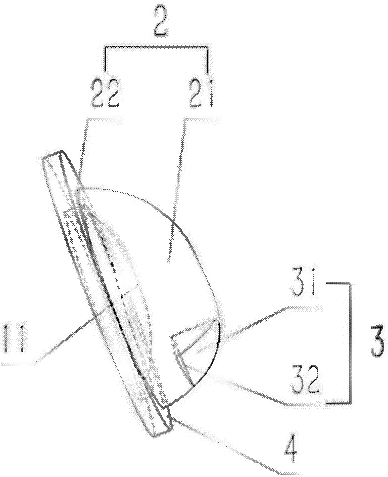
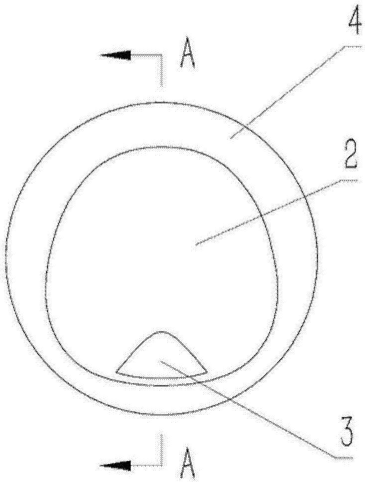
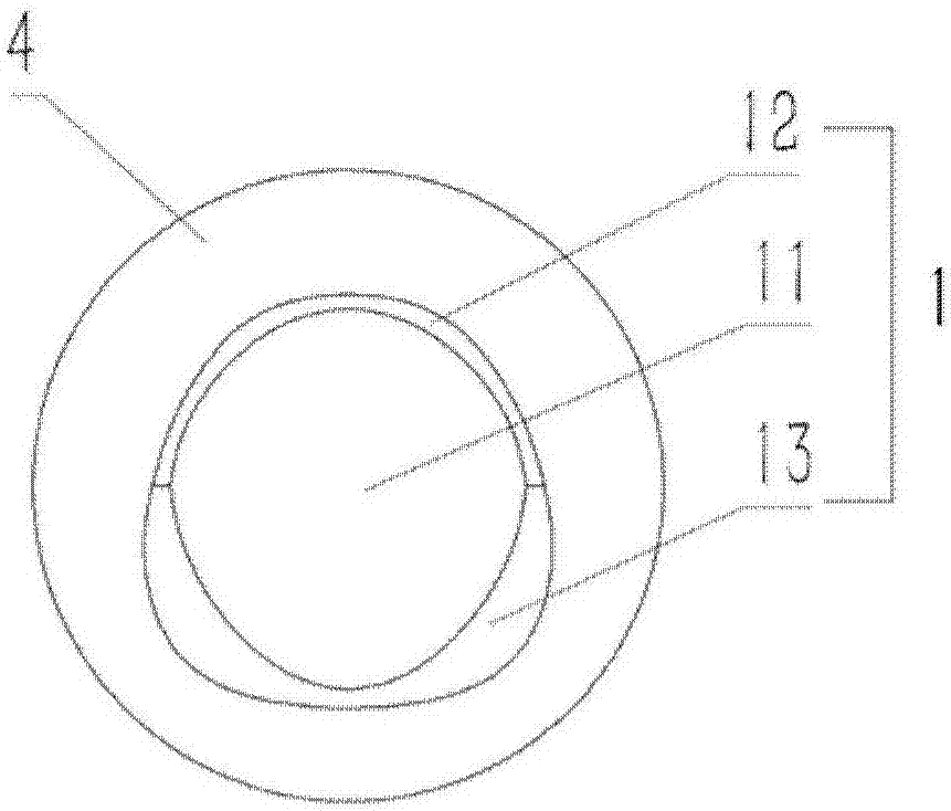
[0051] A LED lamp polarizing lens, Figure 1 to Figure 4 For the perspective view, front view, rear view and cross-sectional view of the LED lamp polarizing lens in the embodiment of the present invention, such as Figure 1 to Figure 4 As shown, the LED lamp polarizing lens mainly includes a light incident surface 1 and a light exit surface 2, the light incident surface 1 and the light exit surface 2 are arranged at corresponding positions on the opposite outer end surface of the lens platform 4, and the light incident surface 1 includes at least a light incident surface free-form surface 11 The free curved surface 11 of the light incident surface is concave in the lens, the light exit surface 2 at least includes a free curved surface 21 of the light exit surface, and the free curved surface 21 of the light exit surface is convex outward of the lens. The distance between the highest point of the free-form surface 11 on the light-incident surface and the second connecting plane...


PUM


Abstract

An LED lamp polarizing light lens comprises a lens body. The bottom of the lens body is provided with a lens platform which is a structure for fixing the LED lamp polarizing light lens. The bottom ofthe lens body is further provided with a cavity for containing an LED light source, a light incident face of the lens body is formed on the inner wall of the cavity, and a light outlet face protrudingoutwards is formed on the surface of the side, opposite to the light incident face, of the lens body. Partial region of the light outlet face is plated with a reflecting film. Compared with the illuminance of a part not plated with the film, the illuminance of the LED lamp polarizing light lens is increased by 1.4 times, the illuminance level below a lamp is improved, the energy saving effect ofthe LED lamp is further shown, meanwhile, the LED lamp polarizing light lens has the technical beneficial effects of being small in size, compact in structure, high in lens efficiency and good in lighting effect, and the technical problems that an existing LED lamp polarizing light lens is small in polarization angle, the illuminance below the lamp is low, and the lamp inclination angle needs to be adjusted during installation can be solved.

Description

technical field [0001] The invention belongs to the technical field of LED lamps, and in particular relates to a polarizing lens for LED lamps. Background technique [0002] LED lights have the characteristics of high luminous efficiency, energy saving, long life, and environmental protection, and are used more and more widely. In the actual engineering application of high-power LED lamps, due to the limitation of installation conditions, there is a situation that the LED light source is installed on the vertical plane of the lamp, but the target lighting surface is the horizontal plane below the lamp. Since the light emitting form of the LED light source is a Lambertian light type, if no secondary optical design is made, the light intensity in the horizontal direction is the strongest, and the luminous flux in the upper half of the space is wasted, and only half of the luminous flux is irradiated on the target lighting surface, which is a serious waste of energy. And the i...

Claims


Application Information

Patent Timeline
Patent Type & Authority Applications(China)
IPC IPC(8): F21K9/20F21V5/04F21V19/00F21V7/00F21Y115/10
CPCF21K9/20F21V5/04F21V7/00F21V19/001F21Y2115/10
Inventor 付万琴胡学功刘月
Owner INST OF ENGINEERING THERMOPHYSICS - CHINESE ACAD OF SCI
Learn More