Radioactive source tank-mounted monitoring device and using method thereof

A monitoring device and radioactive source technology, which is applied in the field of radioactive source canned monitoring devices, can solve the problems of safety, hidden dangers, centralized monitoring of source containers without radioactive sources, etc., and achieve the effect of miniaturization

Inactive Publication Date: 2018-04-06
BC P INC CHINA NAT PETROLEUM CORP +1
View PDF6 Cites 0 Cited by
  • Summary
  • Abstract
  • Description
  • Claims
  • Application Information

AI Technical Summary

Problems solved by technology

[0003] The invention provides a radioactive source canned monitoring device and its use method, which overcomes the shortcomings of the above-mentioned prior art, and can effectively solve the problem in the prior art that there is no centralized monitoring of the source container of the radioactive source and there are potential safety hazards

Method used


Image

  • Radioactive source tank-mounted monitoring device and using method thereof
  • Radioactive source tank-mounted monitoring device and using method thereof
  • Radioactive source tank-mounted monitoring device and using method thereof

Examples


Embodiment 1

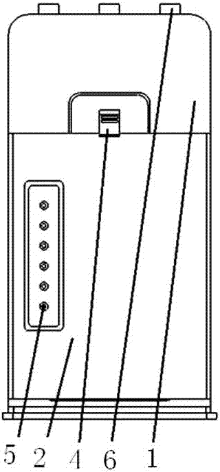
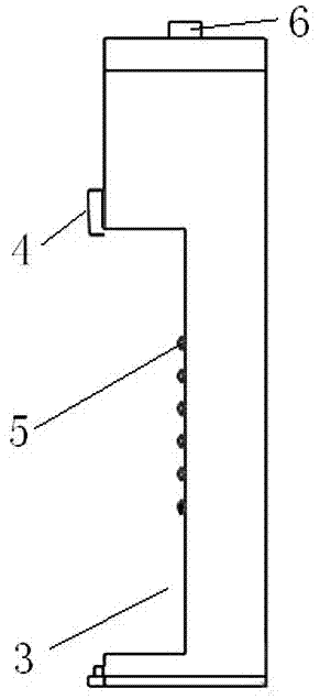
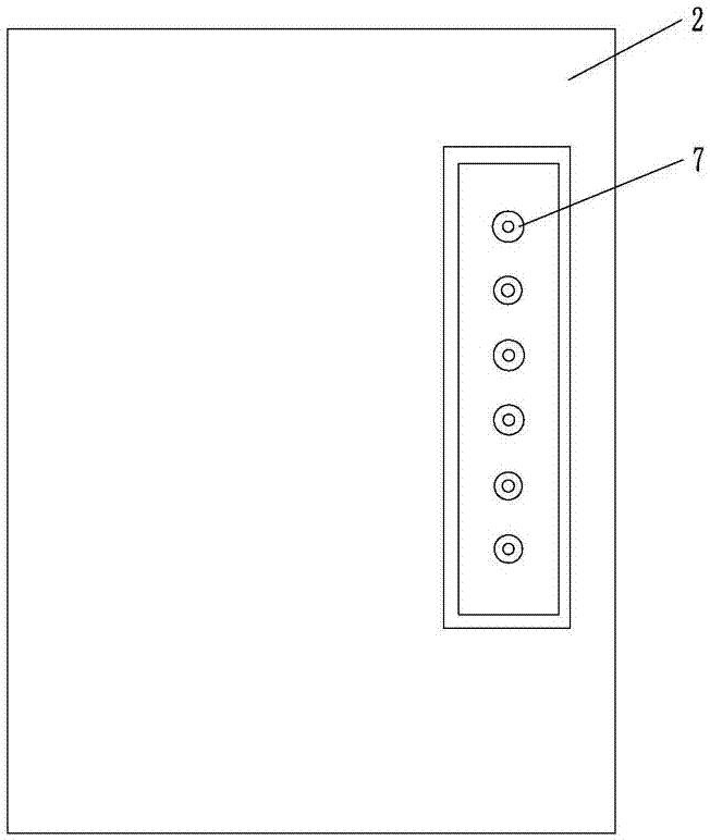
[0023] Embodiment 1: as attached figure 1 , 2 , 3, and 4, the radioactive source tank-mounted monitoring device includes a radioactive source tank body, an intelligent tank-mounted terminal 1 and a battery 2, the radioactive source tank body is an internal hollow structure, and the smart tank-mounted terminal 1 is installed in the radioactive source tank Inside the body, a battery slot 3 is provided on the smart tank-mounted terminal 1, a battery pressing piece 4 is fixed on the upper part of the smart tank-mounted terminal 1 and the lower end of the battery pressing piece 4 extends into the battery slot 3, and a battery The contact 7 is provided with a battery contact 5 matching the battery contact 7 in the battery slot 3, and the battery 2 is detachably installed in the battery slot 3 through the battery pressing piece 4, and the battery contact 7 is in contact with the battery slot. The points 5 overlap with each other; a control device is arranged in the intelligent tank-...

Embodiment 2

[0030] Embodiment 2: as attached figure 1 , 2 , 3, and 4, the method for using the radioactive source tank-mounted monitoring device includes the following steps:

[0031] The first step is to install the battery on the smart canned terminal 1; push the battery pressing piece 4 away, align the battery contact 7 with the battery slot contact 5 and put it into the battery slot 3, and make the battery contact 7 and the battery The slot contacts 5 are overlapped, and then the battery pressing piece 4 is pressed on the upper part of the battery 2, and the battery 2 is clamped;

[0032] The second step is to install the intelligent tank-mounted terminal 1 in the radioactive source tank; place the smart tank-mounted terminal 1 downward as a whole so that the elastic bump 6 is inserted downward into the slot on the inner wall of the bottom surface of the radioactive source tank;

[0033] The third step is to monitor and track the radioactive source online in real time throughout the...


PUM


Abstract

The invention relates to the technical field of radioactive source monitoring and to a radioactive source tank-mounted monitoring device and a using method thereof. The radioactive source tank-mountedmonitoring device includes a radioactive source tank body, an intelligent tank-mounted terminal and a battery. The radioactive source tank body has an internal hollow structure. The intelligent tank-mounted terminal is installed inside the radioactive source tank body and provided with a battery slot. A battery slice is fixed to the intelligent tank-mounted terminal and the lower end of the battery slice extends into the battery slot. A battery contact is arranged on the battery. A battery slot contact is arranged in the battery slot and matches the battery contact. The upper part of the battery is detachably installed in the battery slot through the battery piece. The battery contact and the battery slot contact coincide with each other. A control device is disposed in the intelligent tank-mounted terminal. The radioactive source tank-mounted monitoring device achieves three-in-one real-time online monitoring. The intelligent tank-mounted terminal performs online real-time radiationdose monitoring, online real-time positioning monitoring, and radioactive source basic information management on a radioactive source and a radioactive source database.

Description

technical field [0001] The invention relates to the technical field of tank-mounted radioactive source monitoring, and relates to a radioactive source tank-mounted monitoring device and a method for using the same. Background technique [0002] At present, radioactive logging is an indispensable logging method, which can solve many geological problems. However, at the same time, radioactive sources, especially those with high risk of Class III or above, have high-energy ionizing ray particles, and the radiation is extremely dangerous to the human body. Casualties and even malignant accidents may occur when they are out of control. Regional pollution incidents. Due to the strong fluidity of related operations, the lack of specific identification of the shape, and the many links in the use process, once lost or stolen by criminals, it will cause extremely serious and bad consequences for individuals and society. Therefore, the use of radioactive sources Effective supervision...

Claims


Application Information

Patent Timeline
Patent Type & Authority Applications(China)
IPC IPC(8): G01T1/02
CPCG01T1/02
Inventor 隆山严民贾红兵陈军胜刘广杰陈猛
Owner BC P INC CHINA NAT PETROLEUM CORP
Why Eureka
Try Eureka