
Transformer fault monitoring device and system

A technology of transformer fault and monitoring device, applied in transformer testing, measuring devices, instruments, etc., can solve problems such as affecting power supply, high failure rate of power transformers, and incompatible maintenance development trends.

Inactive Publication Date: 2018-06-12
STATE GRID SHANDONG ELECTRIC POWER COMPANY RIZHAOPOWER SUPPLY
View PDF6 Cites 7 Cited by
  • Summary
  • Abstract
  • Description
  • Claims
  • Application Information

AI Technical Summary

Problems solved by technology

The high failure rate of power transformers not only greatly affects the safe operation of the power system, but also causes huge economic losses to power companies and power users
[0003] How long does the transformer run or how many faults need to be overhauled? At present, there is no scientific conclusion and unified standard. In order to improve the reliability of the power system operation and reduce the economic losses caused by faults and accidents, the transformer should be regularly insulated. preventive test
However, conventional preventive tests require power failure of the transformer. On the one hand, it will affect the normal power supply. On the other hand, some important data cannot be tested during the power failure, which affects the reliability of the monitoring results, and the switching times of the transformer will be increased during regular maintenance. As a result, the service life of the transformer is affected, and the economy of the grid operation is greatly reduced.
[0004] Therefore, the conventional regular preventive test method does not adapt to the development trend of modern condition maintenance, and has the problems of low reliability of monitoring results, poor economy of power grid operation, and affecting users' daily electricity consumption.

Method used


Image

  • Transformer fault monitoring device and system
  • Transformer fault monitoring device and system
  • Transformer fault monitoring device and system

Examples


Embodiment 1

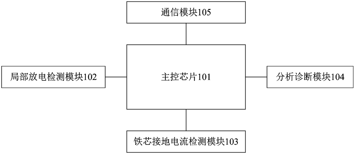
[0043] figure 1A schematic structural diagram of a transformer fault monitoring device provided in an embodiment of the present invention, as shown in figure 1 As shown, the transformer fault monitoring device includes a main control chip 101 , and a partial discharge detection module 102 , an iron core ground current detection module 103 , an analysis and diagnosis module 104 and a communication module 105 respectively connected to the main control chip 101 .

[0044] The partial discharge detection module 102 is used to detect partial discharge signals at different positions inside the transformer, and send the partial discharge signals to the main control chip 101 . The core ground current detection module 103 is used to detect the ground leakage current of the transformer core, and send the ground leakage current to the main control chip 101 . The main control chip 101 is used to receive the partial discharge signal and the ground leakage current, and send them to the ana...

Embodiment 2

[0062] Figure 4 A structural schematic diagram of a transformer fault monitoring system provided by an embodiment of the present invention, as shown in Figure 4 As shown, the transformer fault monitoring system includes a monitoring terminal 42 and a transformer fault monitoring device 41 as in the first embodiment above. The transformer fault monitoring device 41 is communicatively connected with the monitoring terminal 42 .

[0063]In the embodiment of the present invention, the transformer fault monitoring device includes a main control chip, and a partial discharge detection module, an iron core ground current detection module, an analysis and diagnosis module, and a communication module respectively connected to the main control chip; the partial discharge detection module is used to detect transformer Partial discharge signals at different positions inside, and send the partial discharge signals to the main control chip; the core grounding current detection module is ...


PUM


Abstract

The invention provides a transformer fault monitoring device and system, wherein the transformer fault monitoring device includes a main control chip and a partial discharge detection module, an ironcore grounding current detection module, an analysis and diagnosis module, and a communication module respectively connected with the main control chip. The partial discharge detection module detectspartial discharge signals at different positions in the transformer. The iron core grounding current detection module detects a ground leakage current of the iron core of the transformer. The main control chip receives and sends the partial discharge signals and the ground leakage current to the analysis and diagnosis module, packages the partial discharge signals, the ground leakage current and adiagnostic result returned by the analysis and diagnosis module, generates monitoring data, and sends the monitoring data to a monitoring terminal through the communication module, thereby achievingonline real-time monitoring of the transformer, improving the reliability of monitoring results and increasing the service life of the transformer, then improving the economy of power grid operation and the user experience.

Description

technical field [0001] The invention relates to the technical field of fault monitoring, in particular to a transformer fault monitoring device and system. Background technique [0002] The transformer is the most expensive and most important primary piece of equipment in the power system. It is also the equipment with the most complex structure and high failure rate. The safe operation of the transformer is of great significance to ensure the reliability of power supply. The high failure rate of power transformers not only greatly affects the safe operation of the power system, but also causes huge economic losses to power companies and power users. [0003] How long does the transformer run or how many faults need to be overhauled? At present, there is no scientific conclusion and unified standard. In order to improve the reliability of the power system operation and reduce the economic losses caused by faults and accidents, the transformer should be regularly insulated. ...

Claims


Application Information

Patent Timeline
IPC IPC(8): G01R31/02
CPCG01R31/62
Inventor 李娜郁章伟李伟潘曰涛郭伟红任妍韩晓延凯王森田利坤
Owner STATE GRID SHANDONG ELECTRIC POWER COMPANY RIZHAOPOWER SUPPLY
Learn More