Convenient-to-clean de-dusting head device

A dust removal head and cleaning technology, applied in the direction of coupling device, connecting device parts, electrical components, etc., can solve the problems of inconvenient disassembly and assembly of the dust collector, clogging of the dust removal head, difficult disassembly, etc., to increase the efficiency of disassembly and replacement, convenient Disassembly and replacement, the effect of avoiding electric shock accidents

Inactive Publication Date: 2018-04-06
张建松
View PDF1 Cites 0 Cited by
  • Summary
  • Abstract
  • Description
  • Claims
  • Application Information

AI Technical Summary

Problems solved by technology

[0002] The dust collector is used to absorb the dust from the air or the bottom surface to achieve the cleaning effect. After each dust removal work of the dust collector, a certain amount of dust will accumulate in the dust removal head. Over time, it will cause the internal blockage of the dust removal head, affect the dust removal efficiency, and will breed a large number of bacteria
Most of the existing dedusting heads and dedusting bodies are fixedly connected, which is difficult to disassemble. Some dust collectors fastened by screws are also very inconvenient to disassemble, which is not conducive to regular cleaning and maintenance. A few detachable dust collectors are charged internally after disassembly The electric board is exposed, which can easily lead to safety accidents

Method used


Image

  • Convenient-to-clean de-dusting head device
  • Convenient-to-clean de-dusting head device
  • Convenient-to-clean de-dusting head device

Examples


Embodiment Construction

[0020] The preferred embodiments of the present invention will be described in detail below in conjunction with the accompanying drawings, so that the advantages and features of the present invention can be more easily understood by those skilled in the art, so as to define the protection scope of the present invention more clearly.

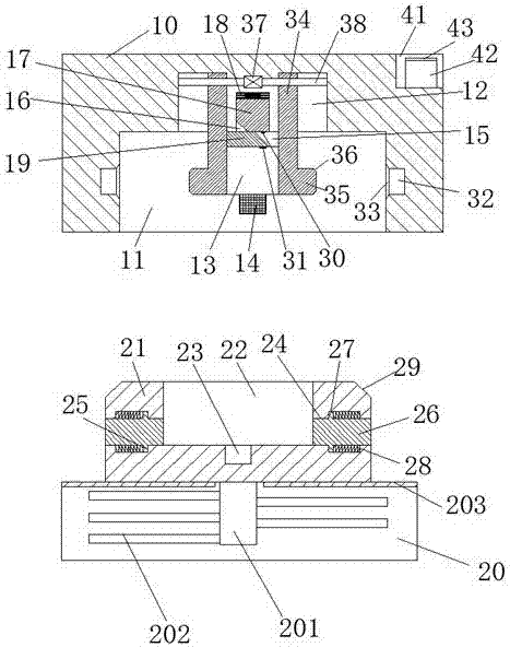
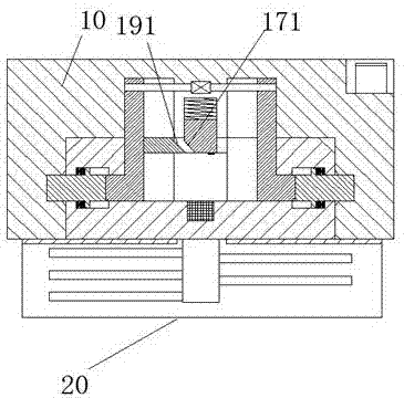
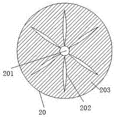
[0021] refer to Figure 1-3 The dust removal head device shown is easy to clean, including a dust removal body 10 and a dust removal head 20 for cooperating with the dust removal body 10 to connect and supply power. The top wall is provided with a first sliding joint groove 12, and two driving guides are arranged in the first sliding joint groove 12, and each of the driving guides includes a downward extending into the insertion cavity 11. The first sliding joint plate 34 and the driving protrusion 35 arranged on the outer side of the bottom of the first sliding joint plate 34 are arranged between the two driving guides with the center of the top...


PUM


Abstract

The invention discloses a convenient-to-clean de-dusting head device. The device comprises a de-dusting machine body and a de-dusting head which is in matched connection with the de-dusting machine body so as to supply power for the de-dusting machine body; an insertion cavity is formed at the bottom surface of the de-dusting machine body; a first sliding groove is formed in the top wall of the insertion cavity; two driving and guiding components are symmetrically disposed at the left and right side of the first sliding groove; and each driving and guiding component includes a first sliding plate extending downwards into the insertion cavity and a driving and guiding protrusion head disposed at the external side of the bottom of the first sliding plate. The convenient-to-clean de-dusting head device of the invention has the advantages of simple overall structure, safe and convenient operation, and convenience in disassembly, maintenance and cleaning. With the convenient-to-clean de-dusting head device of the invention adopted, electric shock accidents occurring during the installation, disassembly and replacement of the de-dusting head can be avoided, the life safety of staff can be ensured, and therefore, the convenient-to-clean de-dusting head device is suitable for being popularized.

Description

technical field [0001] The invention relates to the technical field of dust removal, in particular to an easy-to-clean dust removal head device. Background technique [0002] The dust collector is used to absorb the dust from the air or the bottom surface to achieve the cleaning effect. After each dust removal work of the dust collector, a certain amount of dust will accumulate in the dust removal head. Over time, it will cause the internal blockage of the dust removal head, affect the dust removal efficiency, and will breed a large number of bacteria. Most of the existing dust collectors are fixedly connected with the dust collector body, which is difficult to disassemble. Part of the dust collectors fastened by screws is also very inconvenient to disassemble, which is not conducive to regular cleaning and maintenance. A few detachable dust collectors are charged internally after disassembly. The electric board is exposed, which can easily lead to safety accidents. Conte...

Claims


Application Information

Patent Timeline
Patent Type & Authority Applications(China)
IPC IPC(8): H01R13/629H01R13/639H01R13/642H01R13/633H01R13/631
CPCH01R13/629H01R13/631H01R13/633H01R13/639H01R13/642
Inventor 张建松
Owner 张建松
Why Eureka
Try Eureka