An elastic wave vector imaging method and device, a storage medium and an apparatus

An imaging method and elastic wave technology, applied in the field of seismic exploration, can solve the problems of destroying wave field information and not being able to apply seismic numerical simulation algorithms well, and achieve the effect of accurate reflection information

Inactive Publication Date: 2018-04-10
BC P INC CHINA NAT PETROLEUM CORP +2
View PDF4 Cites 12 Cited by
  • Summary
  • Abstract
  • Description
  • Claims
  • Application Information

AI Technical Summary

Benefits of technology

This technology does this by applying an equation called Elastwave Equation (EW) onto multiple component signals without decompositing them into different parts or performing certain calculations before analyzing each part separately. By doing that it allows for precise analysis with less computational effort compared to traditional methods like Fourier transforms which require complex mathematical operations.

Problems solved by technology

Technological Problem: Current Ground Impulse Acoupling (GIS) techniques require separating longitudinally and laterally waves from each other before performing correlation analysis or depth mapping. These processes result in errors when combining two types of signals together without overlapping their signal parts. Additionally, current methods like harmonic splitting suffer from imperfections called CSEI (Coefficient Error Vector Integrity).

Method used


Image

  • An elastic wave vector imaging method and device, a storage medium and an apparatus
  • An elastic wave vector imaging method and device, a storage medium and an apparatus
  • An elastic wave vector imaging method and device, a storage medium and an apparatus

Examples


Embodiment Construction

[0035] In order to make the purpose, technical solutions and advantages of the embodiments of the present invention more clear, the embodiments of the present invention will be further described in detail below in conjunction with the accompanying drawings. Here, the exemplary embodiments and descriptions of the present invention are used to explain the present invention, but not to limit the present invention.

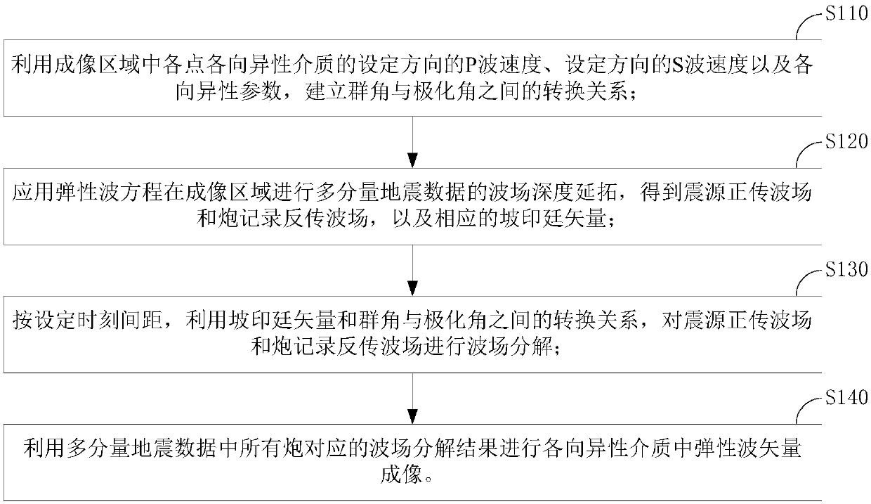
[0036] figure 1 It is a schematic flowchart of the elastic wave vector imaging method of the embodiment of the present invention. Such as figure 1 As shown, the elastic wave vector imaging method of the embodiment of the present invention may include:

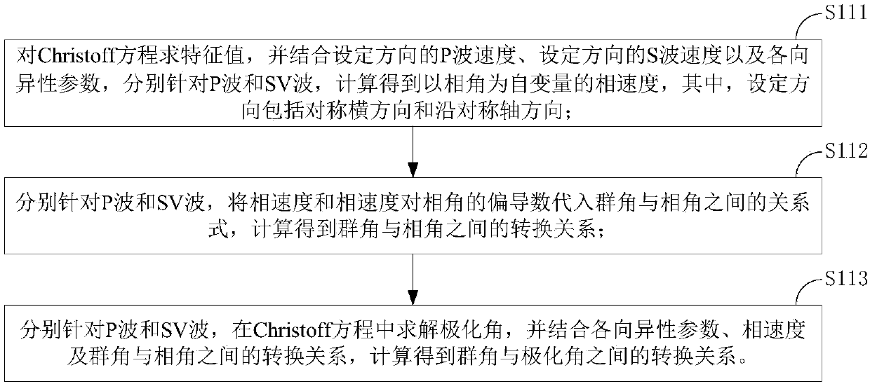
[0037] Step S110: using the P-wave velocity in the set direction, the S-wave velocity in the set direction, and anisotropy parameters of the anisotropic medium at each point in the imaging area to establish a conversion relationship between the group angle and the polarization angle;

[0038] Step S120: applying the...


PUM


Abstract

The invention provides an elastic wave vector imaging method and device, a storage medium and an apparatus. The method comprises the steps of building a conversion relation between group angles and polarizing angles by using the P wave speed of a set direction of an anisotropic medium of each point in an imaging area, the S wave speed of each set direction and anisotropic parameters; using an elastic wave equation to perform wave field depth prolongation of multi-component earthquake data in the imaging area to obtain a focus forward propagation wave field and a shot record back propagation wave field and corresponding Poynting vectors; according to set time intervals, decomposing the focus forward propagation wave field and the shot record back propagation wave field by using the Poyntingvectors and the conversion relation between group angles and polarizing angles; performing vector imaging of elastic waves in anisotropic media by using wave field decomposition results correspondingto all shots in the multi-component earthquake data. The imaging efficiency and accuracy can be improved.

Description


Claims


Application Information

Patent Timeline
Owner BC P INC CHINA NAT PETROLEUM CORP
Why Eureka
Try Eureka